

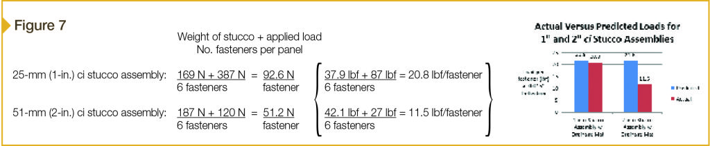
The results of the testing showed the fasteners and fastening schedule were adequate to resist the dead load of the cladding, particularly for the 25-mm insulation assembly, where measured load capacity was 95 percent of predicted values, and an applied load of 387 N (87 lbf) was held at the deflection limit. For the 51-mm insulation assembly, measured load capacity was 53 percent of predicted values, while an applied load of 120 N (27 lbf) was held at the deflection limit. Taking the applied load plus dead load of the cladding, actual loads at the deflection limit were then calculated (Figure 7).
Long-term creep effects, as evaluated under the test conditions, were also within allowable limits. In fact, for two different panels creep was a maximum of 0.15 mm (0.006 in.), and seemed to be influenced more by relative humidity (RH) conditions in the test environment than the dead load of the cladding over a 45-day period.
Similar creep tests have also been performed in the NYSERDA work and more recently in a study by Building Science Corporation for the U.S. Department of Energy (DOE) Build America program. These studies influenced the selection of the stringent short-term load deflection limit of 0.38 mm (0.015 in.) as a means to control the uncertainty of long-term creep effects which, in real-world conditions, may vary with factors—such as elevated temperatures, thermal cycling, and moisture cycling—that cannot always be simulated in lab tests.
Wind resistance
Resistance to wind is another important structural consideration (as is seismic loading, but that is beyond this article’s scope). Once again, national building codes have not historically provided comprehensive prescriptive attachment schedules for ci-based wall assemblies. However, reference is made in the 2012 and previous editions of the IBC to American Society of Civil Engineers (ASCE) 7, Minimum Design Loads for Buildings and Other Structures, as a basis for wind load.
In turn, ASCE 7 establishes fastener embedment into wood or steel studs as the basis for adequacy of cladding attachment (assuming the cladding itself is adequate to resist loads). Ultimately, pull-out or withdrawal capacity of the fastener from framing is used to determine required fastener spacing in relation to design wind pressures. Whether ci is in the assembly is irrelevant, since the length of fastener can be specified to maintain the required engagement or embedment of the fastener into structural members.
Thus, building codes have historically provided some direction for the verification of ci-based wall assembly resistance to wind loading. The 2015 IBC references American National Standards Institute/Structural Building Components Association (ANSI/SBCA) FS 100, Standard Requirements for Wind Pressure Resistance of Foam Plastic Insulating Sheathing Used in Exterior Wall Covering Assemblies. This standard includes a prescriptive table of design wind pressure loads based on design wind speed and exposure, and also provides direction for testing. Once again, ASTM E330 is listed as one test method, and ASTM E1233, Standard Test Method for Structural Performance of Exterior Windows, Doors, Skylights, and Curtain Walls by Cyclic Air Pressure Differential, as an alternate.
Where engineering analysis or verification through testing is needed, it can generally be accomplished at a reasonable cost, but time, planning, and foresight are needed to fit into the pre-construction schedule. As mentioned earlier, construction of mockup assemblies for a project can also be useful for constructability and construction practice verification, as well as establishing a quality control (QC) benchmark for installation of exterior wall coverings and interface detailing.


I would like to read the article about CI and wish to receive Continuing Ed credits (via quiz?) but do not know how to register.
Please advise.
Reference: Figure 6, the drainage mat dimensional conversions are incorrect. Assuming the mat is 1/4 in thick, it would be 6.35 mm thick.
Continuous insulation seems like a good option for year round energy savings. As I was reading, I noticed that it seems to be an option primarily for businesses. As a homeowner, continuous insulation seems like it would be a good thing to have in my home. Is continuous insulation an option to use in homes as well, or is it just not practical due to size or other factors?