

Gypsum board
Before diving into some custom assembly designs, it is important to note there are additional—though less problematic—discrepancies between the WIJ assemblies and proprietary ICC-ES assemblies related to the gypsum board products, thicknesses, and attachment:
- DCA3 WIJ-1.7 (and APA tested equivalents) calls for 12.7 mm (0.5 in.) Type X gypsum board whereas the ICC-ES tested equivalent assemblies call for 15.8 mm (0.625 in.) Type X gypsum board. Perhaps it is the 38.1 mm (1.5 in.) I-joist flange depth requirement in DCA3 that allows for a reduction in the gypsum board thickness, but whatever the case may be, when developing a “one size fits all” assembly design, one will have to specify the thicker board in order to provide adequate fire protection and retain optionality for the I-joists.
- DCA3 WIJ-2.1 (and APA tested equivalents) allows for any generic Type C gypsum board to be used, while the ICC-ES tested equivalent assemblies list specific approved products: Sheetrock Brand Firecode C in the case of Boise Cascade and NGC Gold Bond Fire-Shield C in the case of Weyerhaeuser/Redbuilt. This discrepancy will be addressed in the hybrid assembly designs in the following section.
- DCA3 WIJ-2.1 (and APA tested equivalents) calls for hat channels rather than the resilient channels required in the ICC-ES test reports. Hat channels and resilient channels typically come in different sizes (22.2 mm [0.875 in.] and 12.7mm [0.5 in.] respectively) leading to dimensional differences in a hybrid assembly should either option be allowed. However, WIJ-2.1 notes, per ASTM E2032, resilient channels may be used in lieu of the hat channels. This substitution is also desirable as resilient channels drive increased acoustic performance.
Practical I-joist assemblies
Ideal I-joist assemblies must meet code requirements for fire, sound, and energy performance—all while maximizing product interchangeability for every component of the assembly. In finding common ground between the various assemblies previously discussed, the approach to the designs below might be described as “generic plus.” The designs reference the generic assemblies in DCA3 (thereby supporting virtually all the I-joist assemblies tested by APA). Then, by reference to specific ICC-ES assemblies, the designs capture the major outliers, as well. As mentioned, the assemblies below are templated off of WIJ 1.7 and WIJ 2.1 (the two generic assemblies supporting fiberglass batt insulation) and have been designed for the following applications: one-hour floor, one-hour roof, two-hour floor, and two-hour roof.
There are two versions of each assembly: a “negotiated” version and a “strict” version. The “strict” assemblies follow the exact letter of the fire tests. While this represents the smoothest path to code acceptance, it comes with some trade-offs including reduced flexibility in allowable products, reduced thermal/acoustical performance, and perhaps increased cost. The “negotiated” assemblies deviate slightly from the exact requirements of the test reports, but in doing so, they address some of the shortcomings of the “strict” assemblies. The path to code acceptance is rockier though, and one should consult with a code official to understand whether such deviations would be deemed acceptable in their jurisdiction.
One-hour floor
The one-hour floor (based on WIJ-1.7) pictured in Figure 1 is straightforward. The difference between the “negotiated” and “strict” assemblies is simply insulation thickness. The increase from 228.6 to 305 mm (9 to 12 in.) batt insulation will result in better acoustic performance and is a relatively minor deviation from the fire test. The added insulation is not necessary, but the increased depth and associated increase in R-value will go a lot further with the roof/ceiling assembly. If additional insulation is desired for the roof assembly, it may as well be included in the floor assembly as well.
One-hour roof
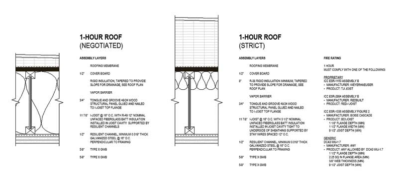
For the roof assembly, pictured in Figure 2, the increased cavity insulation depth in the “negotiated” assembly allows one to achieve R-49 between the joists and, as was mentioned above, this is a relatively common path to prescriptive energy code compliance in colder climate zones. Tapered insulation is provided above the sheathing, and the thickness will vary based on what is needed to provide positive drainage and to move the dew point outside of the roof assembly.
For the “strict” version of the one-hour roof, the entire depth of the joist cavity cannot be insulated and, so, energy code compliance can be achieved with either of two alternatives. The first option (shown in Figure 2) is to reduce the insulation to the 88.9 mm (3.5 in.) minimum required by WIJ-1.7 (insulation is optional in the ICC-ES assemblies) and to comply with the energy code prescriptively by providing continuous rigid insulation above the sheathing (R-38 is the requirement in Washington State).
Another option would be to provide up to R-30 (228.6 mm [9 in.]) insulation in the cavity (tight to the deck above) and only include the amount of rigid insulation above sheathing needed to achieve the required roof assembly U-value. This second option would require that the project comply with the energy code by using the total building performance compliance path.

