DCA3: Designing fire-rated I-joist assemblies
by maz_atta | June 30, 2021 12:46 pm
By Anton Dekom
 [1]
[1]For years, Design for Code Acceptance #3 (DCA3), a document published and maintained by the American Wood Council (AWC), has been the go-to resource for architects working with I-joist assemblies. The document provides designers with a catalogue of non-proprietary, fire-resistance rated I-joist assemblies typically well-known and readily accepted by local building officials.
The wood I-joist (WIJ) assemblies were added to DCA3 in 2001 and were intended to promote the usage of engineered lumber by simplifying the associated design, specification, and permitting processes. Prior to the publication of the WIJ assemblies, architects and engineers had to seek out each I-joist manufacturers’ proprietary literature and fire test documentation to design a custom, non-proprietary assembly or write an open specification. DCA3 made working with I-joists easier by providing a robust set of generic assemblies broadly compatible with most I-joists on the market.
However, in the decades since the WIJ assemblies were first published, revisions to DCA3 have lagged behind developments in the engineered wood industry. Some of the largest I-joist manufacturers have brought products to market that do not comply with DCA3, backed instead by privately commissioned fire test reports based on proprietary assemblies. More specifically, the I-joists which do not comply with DCA3 generally do not meet the minimum dimensional requirements stipulated in the WIJ assemblies. The makers of these joists are major players and cannot simply be excluded from an open specification or generic assembly. The net result is that DCA3 no longer functions as the “one size fits all” standard it once did.
In 2021, designers must once again comb through manufacturer literature and fire test reports1 to design I-joist assemblies compatible with a sufficiently wide-ranging cross section of the I-joist market. As is often the case when referencing multiple proprietary standards, different manufacturers’ specific requirements can conflict with one another. The incompatibility of the various test reports and reference standards makes it difficult to find common ground between generic and proprietary literature.
This article will go into more detail on the shortcomings of both DCA3 and the manufacturer fire tests. The author will demonstrate a few possible avenues for threading the needle between generic and proprietary assemblies and will share some versatile assembly designs aimed at multifamily residential construction: floor and roof assemblies (both one-hour and two-hour rated) that meet code requirements for fire, thermal, and sound. The article will conclude with some thoughts on why the design and specification of I-joist assemblies has become far more complicated than necessary and underscore the continued importance of generic assemblies that work for the whole industry.
I-joist dimensional requirements
Each WIJ assembly included in DCA3 stipulates certain minimum dimensional requirements for the I-joist framing members: overall depth, web width, flange width, and flange depth. In theory, this approach makes it easy for architects and engineers to write open specifications; instead of consulting manufacturer test reports and listing allowable proprietary I-joists (and their compatible companion products), an architect can simply pass on the dimensional requirements in a performance specification, giving the builder on the other end maximum flexibility to competitively bid their lumber package.
Unfortunately, the dimensional constraints listed in DCA3 are no longer in total alignment with the I-joist industry. Of eight I-joist assemblies listed in DCA3, six require a minimum flange depth of 38.1 mm (1.5 in.), a depth that exceeds what is now standard for many manufacturers. Some of the industry’s major players have entry level product lines with flanges as slim as 28.5 mm (1.125 in.) or 31.7 mm (1.25 in.). In many cases these manufacturers also produce I-joists with 38.1 mm (1.5 in.) flange depths, but these are typically heavy-duty joists intended for heavier loads or longer spans. Such joists would be excessive in many applications and typically come at a cost premium.
The remaining assemblies in DCA3 (WIJ-1.3 and WIJ-1.6) stipulate a minimum flange depth of 33.3 mm (1.312 in.), but even this reduced requirement lacks broad compatibility with many I-joist products. The difference may come down to mere sixteenths of an inch, but it is enough to matter when it comes to the applicability of the fire-rated assemblies. Specifications for fire-rated assemblies are always predicated on conformance to the minutest of details, and local code officials can be relied on to nitpick them.
Though it may give cold comfort, it is perhaps a sign of progress that a growing number of I-joists do not meet DCA3’s dimensional prescriptions. When DCA3 was first published, it is likely many I-joists did indeed satisfy all these requirements but, over the years, manufacturers have improved their technologies and found ways to get better performance out of less material. The trend toward smaller flanges is a sign of efficiency — although unfortunately the DCA3 standard has been slow to catch up.
Cavity insulation
 [2]
[2]Horizontal I-joist assemblies must accommodate cavity insulation to work in a broad array of applications. On multifamily residential projects, a fully insulated joist cavity is typically necessary to allow the assembly to be used in roof/ceiling applications. For those seeking prescriptive compliance with the International Energy Conservation Code (IECC) (and aiming to insulate the joist cavity rather than provide continuous insulation above the sheathing) R-49 is the minimum required for climate zones 4 (marine) and higher. Achieving this level of performance with cavity insulation generally entails insulating the entire depth of 302 mm (11.875 in.) I-joist roof/ceiling assembly.
Another reason to fully insulate between I-joists is improved acoustic performance in floor and ceiling applications. Floor assemblies for multifamily projects are typically required by International Building Code (IBC) Chapter 12 to meet minimum sound ratings of sound transmission class (STC) 50 and impact insulation class (IIC) 50. It is relatively common for building owners to ask for their floor assemblies to be designed to exceed these code minimums. Adding mass to a floor assembly improves STC ratings (and to a lesser extent, IIC ratings) and is generally an economical way to increase acoustic performance.
Fiberglass insulation, whether blown-in or blanket, is perhaps the most used material for this application. It has been used in residential construction for decades, is commonly available at hardware stores and lumber yards, and is inexpensive.
While it is also possible to insulate the joist cavity with mineral wool batts, the practice is less common. Mineral wool batts typically do not exceed R-38, which means in colder climate zones two batts must be installed between joists to achieve R-49 and costs add up quickly.
Both DCA3 and the proprietary fire test reports offer insulated assemblies utilizing either fiberglass or mineral wool insulation, though not all (WIJ-1.5 and WIJ-1.6) allow full cavity insulation.2 The DCA3 assemblies allowing insulation list the required thicknesses as minimums, but this is not always the case with proprietary I-joist assemblies. Those tested by the Engineered Wood Association (APA) typically match DCA3 closely and stipulate minimum insulation thicknesses, but assemblies tested by the International Code Council Evaluation Service (ICC-ES) are more restrictive and generally do not allow a 305 mm (12 in.) nominal joist bay to be fully insulated.
Given the need for full cavity insulation, the assemblies below will focus largely on finding common ground between WIJ-1.7 and WIJ-2.1 and the proprietary equivalents of these assemblies. WIJ-1.7 and WIJ-2.1 are the two assemblies in DCA3 allowing for fiberglass insulation, and they have direct corollaries in almost every fire evaluation report.
WIJ-1.7 specifies no minimum or maximum insulation requirement whereas the equivalent assemblies in the ICC-ES test reports3 stipulate a maximum of R-30 or 241.3 mm (9.5 in.) The two-hour assemblies are similar; whereas WIJ-2.1 specifies 76.2 mm (3.5 in.) as the minimum amount of fiberglass insulation, the equivalent ICC-ES tested assemblies4 list 76.2 mm as the maximum.
The ICC-ES test reports provide no option for fully insulating a typical 305 mm (12 in.) I-joist assembly. This appears to be a major oversight and complicates our efforts to craft hybrid generic/proprietary assemblies.
Gypsum board
Before diving into some custom assembly designs, it is important to note there are additional—though less problematic—discrepancies between the WIJ assemblies and proprietary ICC-ES assemblies related to the gypsum board products, thicknesses, and attachment:
- DCA3 WIJ-1.7 (and APA tested equivalents) calls for 12.7 mm (0.5 in.) Type X gypsum board whereas the ICC-ES tested equivalent assemblies call for 15.8 mm (0.625 in.) Type X gypsum board. Perhaps it is the 38.1 mm (1.5 in.) I-joist flange depth requirement in DCA3 that allows for a reduction in the gypsum board thickness, but whatever the case may be, when developing a “one size fits all” assembly design, one will have to specify the thicker board in order to provide adequate fire protection and retain optionality for the I-joists.
- DCA3 WIJ-2.1 (and APA tested equivalents) allows for any generic Type C gypsum board to be used, while the ICC-ES tested equivalent assemblies list specific approved products: Sheetrock Brand Firecode C in the case of Boise Cascade and NGC Gold Bond Fire-Shield C in the case of Weyerhaeuser/Redbuilt. This discrepancy will be addressed in the hybrid assembly designs in the following section.
- DCA3 WIJ-2.1 (and APA tested equivalents) calls for hat channels rather than the resilient channels required in the ICC-ES test reports. Hat channels and resilient channels typically come in different sizes (22.2 mm [0.875 in.] and 12.7mm [0.5 in.] respectively) leading to dimensional differences in a hybrid assembly should either option be allowed. However, WIJ-2.1 notes, per ASTM E2032, resilient channels may be used in lieu of the hat channels. This substitution is also desirable as resilient channels drive increased acoustic performance.
Practical I-joist assemblies
Ideal I-joist assemblies must meet code requirements for fire, sound, and energy performance—all while maximizing product interchangeability for every component of the assembly. In finding common ground between the various assemblies previously discussed, the approach to the designs below might be described as “generic plus.” The designs reference the generic assemblies in DCA3 (thereby supporting virtually all the I-joist assemblies tested by APA). Then, by reference to specific ICC-ES assemblies, the designs capture the major outliers, as well. As mentioned, the assemblies below are templated off of WIJ 1.7 and WIJ 2.1 (the two generic assemblies supporting fiberglass batt insulation) and have been designed for the following applications: one-hour floor, one-hour roof, two-hour floor, and two-hour roof.
There are two versions of each assembly: a “negotiated” version and a “strict” version. The “strict” assemblies follow the exact letter of the fire tests. While this represents the smoothest path to code acceptance, it comes with some trade-offs including reduced flexibility in allowable products, reduced thermal/acoustical performance, and perhaps increased cost. The “negotiated” assemblies deviate slightly from the exact requirements of the test reports, but in doing so, they address some of the shortcomings of the “strict” assemblies. The path to code acceptance is rockier though, and one should consult with a code official to understand whether such deviations would be deemed acceptable in their jurisdiction.
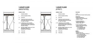
One-hour floor
The one-hour floor (based on WIJ-1.7) pictured in Figure 1 is straightforward. The difference between the “negotiated” and “strict” assemblies is simply insulation thickness. The increase from 228.6 to 305 mm (9 to 12 in.) batt insulation will result in better acoustic performance and is a relatively minor deviation from the fire test. The added insulation is not necessary, but the increased depth and associated increase in R-value will go a lot further with the roof/ceiling assembly. If additional insulation is desired for the roof assembly, it may as well be included in the floor assembly as well.
One-hour roof
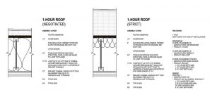 [3]
[3]For the roof assembly, pictured in Figure 2, the increased cavity insulation depth in the “negotiated” assembly allows one to achieve R-49 between the joists and, as was mentioned above, this is a relatively common path to prescriptive energy code compliance in colder climate zones. Tapered insulation is provided above the sheathing, and the thickness will vary based on what is needed to provide positive drainage and to move the dew point outside of the roof assembly.
For the “strict” version of the one-hour roof, the entire depth of the joist cavity cannot be insulated and, so, energy code compliance can be achieved with either of two alternatives. The first option (shown in Figure 2) is to reduce the insulation to the 88.9 mm (3.5 in.) minimum required by WIJ-1.7 (insulation is optional in the ICC-ES assemblies) and to comply with the energy code prescriptively by providing continuous rigid insulation above the sheathing (R-38 is the requirement in Washington State).
Another option would be to provide up to R-30 (228.6 mm [9 in.]) insulation in the cavity (tight to the deck above) and only include the amount of rigid insulation above sheathing needed to achieve the required roof assembly U-value. This second option would require that the project comply with the energy code by using the total building performance compliance path.
Two-hour floor
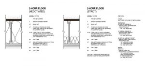 [4]
[4]Like the one-hour floor, the main difference between the “strict” and “negotiated” assemblies is the cavity insulation. In this case, pictured in Figure 3, the insulation depth in the “negotiated” assembly is increased from 76.2 to 305 mm (3.5 to 12 in.), a non-trivial change which should be discussed with the code official. Unlike with the one-hour floor, the increased insulation is doing more work acoustically. Note that WIJ-2.1 lists an IIC of 45 when using vinyl flooring. This is below the code minimum of 50 IIC, so for the “strict” assembly to meet code, the finish floor must be carpet and pad, or a more robust topping slab and sound mat should be specified. The other more minor difference between the “strict” and “negotiated” assemblies is in the gypsum board ceiling. The “negotiated” assembly calls for generic Type C gypsum board; the “strict” assembly calls for a Type C gypsum board product compatible with the relevant fire test. In practice, this means proprietary gypsum board products will be required if one of the ICC-ES tested I-joists is selected.
Two-hour roof
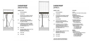 [5]
[5]As with the one-hour roof, a code official’s flexibility regarding cavity insulation thickness will drive the overall approach for the two-hour roof shown in Figure 4 (page 26). If full cavity insulation is permitted, then R-49 can be achieved within the I-joist cavity. If the “strict” assembly is used instead, then the minimum 76.2 mm (3.5 in.) insulation should be installed tight to the deck above. Prescriptive compliance with the energy code can be achieved with continuous rigid insulation above the sheathing. Like the two-hour floor, the Type C gypsum board in the “strict” assembly is contingent on the I-joist installed.
Parting thoughts
The custom assemblies above demonstrate it is indeed possible to find middle ground between the DCA3 WIJ assemblies and independent, proprietary assemblies. The “strict” assemblies following the dictates of both sets of requirements (generic and proprietary) are not perfect, but they are not fatally flawed either. The negotiated assemblies are likely preferred, but code official acceptance is not guaranteed.
So, there are functional solutions, but why this effort is needed at all is a topic worth investigating. Have manufacturers gone rogue? Have the American Wood Council and DCA3 been too slow to adapt? In 2021, there is no reason why the design and specification of I-joist assemblies must be so laborious. In fact, it ought to be dead simple. This simplicity once existed in the form of the DCA3 WIJ assemblies, but it has been lost. Fortunately, there are ways for the industry to correct course.
First, proprietary assemblies should provide a baseline level of compatibility with long-accepted generic industry standards. At a bare minimum, this means allowing full cavity insulation, but ideally it would also entail allowing generic gypsum products to be used as well.
Second (and even better), manufacturers and industry groups should come together and continue to invest in the generic DCA3 WIJ assemblies. This means adding compatibility for I-joists with different dimensional characteristics (either by extrapolating existing test report data or by jointly financing new test reports) to DCA3 and committing to keeping the document abreast of future advances.
I-joists and engineered lumber have seen broad adoption over the last decade, in no small part because of documents like DCA3. The common cause and shared purpose bringing manufacturers and industry groups together under one umbrella—the ethos of collaboration that pushed the entire industry forward—should once again be revived.
 [6]Anton Dekom is an architect at Neiman Taber Architects in Seattle, Washington. His focus is on multifamily residential construction.
- [Image]: https://www.constructionspecifier.com/wp-content/uploads/2021/06/dreamstime_m_164097544.jpg
- [Image]: https://www.constructionspecifier.com/wp-content/uploads/2021/09/DEKOM-1-HOUR-I-JOIST-FLOOR.jpg
- [Image]: https://www.constructionspecifier.com/wp-content/uploads/2021/09/DEKOM-1-HOUR-I-JOIST-ROOF.jpg
- [Image]: https://www.constructionspecifier.com/wp-content/uploads/2021/09/DEKOM-2-HOUR-I-JOIST-FLOOR.jpg
- [Image]: https://www.constructionspecifier.com/wp-content/uploads/2021/09/DEKOM-2-HOUR-I-JOIST-ROOF.jpg
- [Image]: https://www.constructionspecifier.com/wp-content/uploads/2021/09/Dekom-1.jpg
Source URL: https://www.constructionspecifier.com/dca3-designing-fire-rated-i-joist-assemblies/