

Problem #3: Improper building expansion joint configuration
Not to be overlooked, expansion joint configuration is equally important to accommodating building movements.
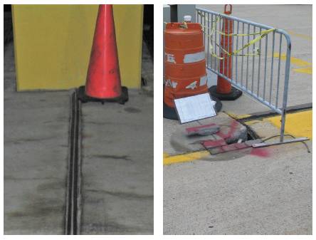
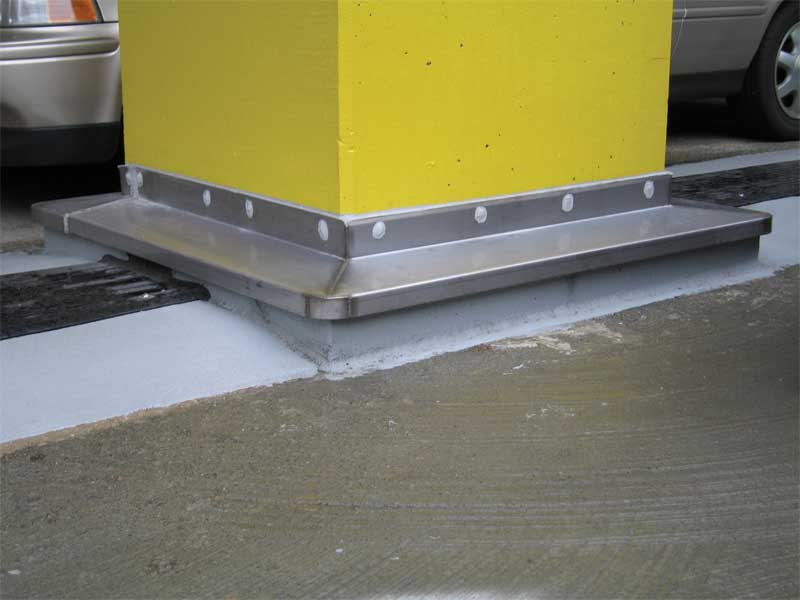
Expansion joint seals are typically designed to work in tension across the joint width. As shown in Figure 6, oddly shaped expansion joints may include many right angles to fit the joint around columns and walls. When an expansion joint includes right angles, both tension and shear forces are applied to the expansion joint seal. Shear forces can result in failures at transitions and shear locations, leaving the joint vulnerable to water infiltration. At a similar project, the design team intended to include right angles in their expansion joint to accommodate a column penetration. However, they did not adequately plan for incorporation of the expansion joint seal within the substrate materials along the vertical column face parallel to the anticipated movement. There was no room for continuation of the expansion joint seal, and it was terminated at the face of the column. Instead of the planned expansion joint seal, a urethane sealant joint, which could not accommodate the anticipated shear movement, was installed along the vertical column face. One potential repair for either condition listed above would be to raise the shear portion of the expansion joint above the drainage plane and cover the joint with counterflashing, as shown in Figure 7.
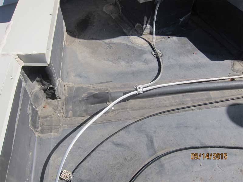
In addition to poorly designed joint shape, other problems involving joint configuration occur at slab-to-wall and wall-to-roof transitions. Figure 8 depicts a roof/parapet wall interface where the roof expansion joint is not continued up the interior face of the parapet. Roofing patches and sealant at the metal coping joints are present, indicating failures at these locations. At another structure, an exterior masonry wall was located above an exterior concrete slab and ran parallel to an expansion joint in the slab. The masonry veneer was designed to be supported on one side of the expansion joint while tied back to the structure on the other side of the joint, as shown in Figure 9 (page 27). If installed in this way, movement at the expansion joint would have pulled the masonry veneer away from the backup. The lack of cut sections in the architectural drawing set meant that this issue was not discovered until construction. Ultimately, the masonry veneer was supported by shelf angles directly over the expansion joint and exterior exposed slab. The as-built gap provided between the slab topside and the underside of the shelf angle was approximately 25 mm (1 in.), which did not allow for installation of the expansion joint seal. Visible in Figure 10 (page 27), the waterproofing solution consisted of flexible flashing and face-sealed cover plates over the expansion joint, under the supported veneer brick and extending out onto the exposed exterior concrete slab. This solution eventually failed, leaving masonry wall removal and expansion joint reconfiguration as the next step in remediation of the joint.
For successful expansion joint configuration, the design team should avoid oddly shaped expansion joints and check transition details carefully. Expansion joint seals should not be installed to resist shear movements unless the seal material is selected specifically to accommodate these movements. In exposed conditions, where possible, the expansion joint seal should be installed above the drainage level, for example, within a curb. The designers should also discuss the feasibility of their transition details with the contractor regarding both installation and future maintenance.
Problem #4: Lack of design team coordination for building expansion joint seal material capacity versus actual movements
As mentioned before, the structural engineer is responsible for calculating expected movement at expansion joints and sharing their predictions with the rest of the design team. The architect uses this information to select an expansion joint seal with sufficient material capacity which can accommodate the anticipated movement. If the structural engineer fails to predict movement accurately, or the lines of communication breakdown, the seal selected by the architect could have insufficient capacity.

