

For proper delegation of design, the contract documents need to clearly define acceptable project material requirements and project-specific conditions and constraints. The specifications should include items such as:
- design loads meeting or exceeding code requirements;
- maximum post spacing as determined by limitations of the supporting structural element;
- geometry of the supporting concrete member (including minimum edge and corner distances);
- whether supplementary reinforcement and cracked or uncracked concrete are assumed; and
- compressive strength of concrete.
The submittals from the delegated designer should include calculations and sealed shop drawings to be reviewed by the EOR to ensure there are proper load paths to the supporting structural elements, the structural element can support the proposed rail post base reactions, and the anchorage locations are coordinated with embedded items in the concrete.
Rail post anchorage 101
The design of railing systems begins with the building code. The International Building Code (IBC) provides minimum required loading on railing systems and their anchorages:
A concentrated force of 0.89 kN (200 lb) or 0.73 kN/m (50 plf) applied in any direction to the top horizontal rail. When rail post spacing exceeds 1.2 m (4 ft), the 0.73 kN/m force will govern it. These loads should be transmitted to the post anchorages and from there into the substrate. The choice of anchorage configuration and the substrate—curb, slab edge, etc.—affect the transmission of these loads.
The two most commonly used rail post anchorage configurations are:
1) embedment of the post in grout in a sleeved or core-drilled pocket (Figure 2); and
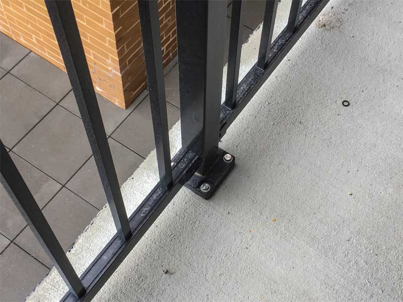
2) a surface-mounted base plate with post-installed anchors (Figure 3).
Variations of these two configurations can be found in several resources, including the “Construction Details” section of the National Association of Architectural Metal Manufacturers’ (NAAMM’s) AMP 521, Pipe Railing Systems Manual including Round Tube. For non-pipe railing systems, reference should be made to manufacturer’s details that may require additional design. Wall brackets are also common, but typically only offer lateral support locally at the railing terminations. Both embedment and surface-mounted configurations have their comparative advantages in design and constructability, and the choice often depends on cost, substrate configuration, project sequencing, or a combination of all three. With the base plate configuration, both the anchor type and design parameters are critical. The grouting material is important for the embedded rail post configuration. With both arrangements, avoidance of interference with other embedded objects (most commonly reinforcing steel) and edge distance are critical. Allowable edge distance is greatly affected by the presence/absence of confining steel reinforcement between the post and the edge.
The 2018 IBC refers to Chapter 17, “Anchoring to Concrete,” of the American Concrete Institute (ACI) 318-14, Building Code Requirements for Structural Concrete and Commentary (Appendix D in earlier versions of the standard), for the structural design of anchoring to concrete. Surface-mounted rail post base plates resist horizontal rail loadings by means of a moment couple between tensile loads in the anchors and compression bearing between the base plate and the concrete surface. While the surface-mounted base connection can
be easily designed by following the provisions in ACI 318 (Chapter 17) and AMP 521, the design of an embedded rail post can be more challenging.
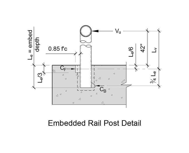
With the embedded rail post configuration, the horizontal rail loading is resisted by a shear couple in the implanted portion (Figure 4). Engineers often struggle with, and the industry provides little guidance for, the calculation of the imposed shear load on the concrete. One methodology used by the authors was developed by the Precast Concrete Institute (PCI) and is described in a PCI Journal article authored by Charles H. Raths in 1974. In this article, a methodology is offered for determining the distance between and position of the embedded shear couple (Figure 4). Once the shear force (CF) at the top of the embedment is determined, provisions in Chapter 17 can be used to determine if the surrounding concrete can resist the imposed shear force.
Concerns persist
Some rail post anchorage configurations are simply not buildable if they are to accommodate all the various construction tolerances that need to be considered. For example, design of a rail post set in a concrete curb needs to accommodate railing setting tolerances (typically fixed by the manufacturer), reinforcement steel placement tolerances, and cover requirements (ACI 117, Specification for Tolerances for Concrete Construction and Materials), post edge distances (determined by design), and deviation of formed surfaces (ACI 117). A 200-mm (8-in.) wide curb is too narrow to accommodate a 100-mm (4-in.) wide embedded hole, or provide enough edge distance for an anchored base plate.
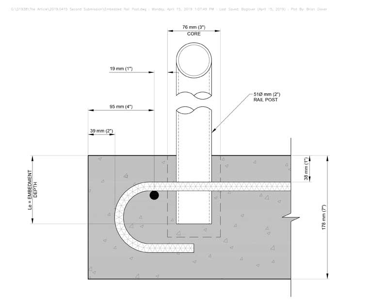
Similarly, thin concrete balconies also present issues if the post anchorage is not coordinated with reinforcement steel location and slab thickness. Figure 5 depicts an embedded rail post with a 150-mm (6-in.) edge distance (dimensioned from the slab edge to center of the rail post). Considering a preferred edge bar placement at the top location (right before the bend radius), a clearance of 20 mm (¾ in.) remains to account for construction tolerances. Moving the railing post closer to the slab edge would require the relocation of the edge bar or complete elimination of the edge reinforcement all together, but the removal would decrease the concrete breakout capacity.


I would love to post this story on my website. Is that possible?