Design considerations for rail post anchorage into concrete
by sadia_badhon | June 7, 2019 11:18 am
by Robert C. Haukohl, PE, Bartosz Lipinski, PE, SE, and Matthew L. Wagner, SE
 [1]
[1]Railing systems are ubiquitous in the built environment, and as such, their appearance is more highly considered than functionality. Minimum loading requirements for railing systems have been part of codes for about as long as these standards have been in existence, and although railing systems may be built and tested to meet code loading requirements, and manufacturers provide generic mounting details, rail post anchorages still need to be formally designed either by the designer of record or by a specialty engineer who is retained through the delegated design process.
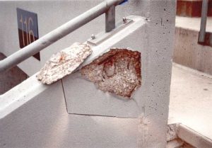
Rail post anchorage design is often not properly emphasized, or is altogether forgotten during the design process. The design and installer/manufacturer teams often see anchorage design as the others’ responsibility. Critical design and coordination issues are either not considered or left to be resolved in the field. Someone needs to verify the anchorage is capable of supporting code required loads, coordinate the trades involved so the anchorage does not interfere with other construction, and ensure post holes will not explode (Figure 1). This person can be the architect, engineer of record (EOR), delegated designer, contractor, or all of the above depending on project size and delivery method.
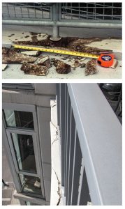 [2]
[2]Images courtesy Raths, Raths & Johnson, Inc.
The authors see the same design and construction errors made repeatedly, including:
- the use of expansive grout or grout that weathers or disintegrates with repeated exposure to water;
- lack of consideration of detail-specific design constraints, such as edge distance and anchor size; and
- absence of coordination with embedded items, mostly reinforcement steel.
If the drawings and/or the specifications are incomplete or unclear, or if not clarified through the request for information (RFI) process, the anchorages may not meet code, resulting in spalled concrete, loose railings, or severed reinforcing steel.
EOR or delegated design
The root cause of most rail post anchorage issues is a failure to identify the team responsible for anchorage design, or even that rail post anchorages need to be designed at all. It is not enough to simply specify a railing system without consideration for anchorage and without the EOR’s input on whether loading from the selected system can successfully be transmitted to the structure. No one seems to want to do the design for capability, liability, or cost reasons.
 [3]
[3]A disconnect between the design and installer/manufacturer teams often occurs because the language in the specification or referenced standard either does not mention anchorage design directly or implies the inclusion of anchorage design in the manufacturer’s installation instructions. ASTM E985, Standard Specification for Permanent Metal Railing Systems and Rails for Buildings, provides guidance specific to metal railing design. It says, railings shall be installed per product manufacturer’s specifications. However, do those project specifications include anchorage design? Manufacturers generally make sure the railings themselves meet code loading requirements and provide generic mounting details, but do not offer anchorage design.
One option the architect may select is to delegate the anchorage design to a licensed specialty structural engineer retained by the installer, supplier, or fabricator of the railing system. Before rail post anchorage design can be delegated, the EOR should review the proposed rail post architectural details, locations, and spacing to confirm a proper load path is present and the structure is capable of supporting the code-required railing loads. Although a delegated designer may be able to identify potentially problematic anchorage configurations, they are not required to confirm the structural capacity of the supporting members the railing assemblies are being anchored into. As the EOR has a better understanding of the structure as a whole, and his/her specifications and reviews are in many ways redundant to the specialty engineer’s design, it may be simpler and more cost effective to have them perform the anchorage design, thereby reducing overall effort, mishaps, and miscommunication.
| ● International Building Code (IBC), International Code Council (ICC), 2018. ● The American Concrete Institute (ACI) 318-14, Building Code Requirements for Structural Concrete. “Embedded Structural Steel Connections” by Charles H. Raths for PCI Journal, May-June 1974. ● ASTM E985, Standard Specification for Permanent Metal Railing Systems and Rails for Buildings. ● ASTM C1107, Standard Specification For Packaged Dry, Hydraulic-Cement Grout (Nonshrink). ● ASTM E1481, Standard Terminology of Railing Systems and Rails for Buildings. The National Association of Architectural Metal Manufacturers’ (NAAMM’s), AMP 521-01 R2012, Pipe Railing Systems Manual including Round Tube, fourth edition (2001, revised 2012). ● The United States Code of Federal Regulations (CFR), Title 29 Part 1910.23, Guarding Floors and Wall Openings and Holes. |
 [4]
[4]For proper delegation of design, the contract documents need to clearly define acceptable project material requirements and project-specific conditions and constraints. The specifications should include items such as:
- design loads meeting or exceeding code requirements;
- maximum post spacing as determined by limitations of the supporting structural element;
- geometry of the supporting concrete member (including minimum edge and corner distances);
- whether supplementary reinforcement and cracked or uncracked concrete are assumed; and
- compressive strength of concrete.
The submittals from the delegated designer should include calculations and sealed shop drawings to be reviewed by the EOR to ensure there are proper load paths to the supporting structural elements, the structural element can support the proposed rail post base reactions, and the anchorage locations are coordinated with embedded items in the concrete.
Rail post anchorage 101
The design of railing systems begins with the building code. The International Building Code (IBC) provides minimum required loading on railing systems and their anchorages:
A concentrated force of 0.89 kN (200 lb) or 0.73 kN/m (50 plf) applied in any direction to the top horizontal rail. When rail post spacing exceeds 1.2 m (4 ft), the 0.73 kN/m force will govern it. These loads should be transmitted to the post anchorages and from there into the substrate. The choice of anchorage configuration and the substrate—curb, slab edge, etc.—affect the transmission of these loads.
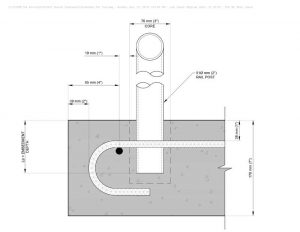
 [5]
[5]The two most commonly used rail post anchorage configurations are:
1) embedment of the post in grout in a sleeved or core-drilled pocket (Figure 2); and
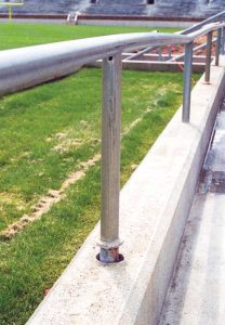
2) a surface-mounted base plate with post-installed anchors (Figure 3).
Variations of these two configurations can be found in several resources, including the “Construction Details” section of the National Association of Architectural Metal Manufacturers’ (NAAMM’s) AMP 521, Pipe Railing Systems Manual including Round Tube. For non-pipe railing systems, reference should be made to manufacturer’s details that may require additional design. Wall brackets are also common, but typically only offer lateral support locally at the railing terminations. Both embedment and surface-mounted configurations have their comparative advantages in design and constructability, and the choice often depends on cost, substrate configuration, project sequencing, or a combination of all three. With the base plate configuration, both the anchor type and design parameters are critical. The grouting material is important for the embedded rail post configuration. With both arrangements, avoidance of interference with other embedded objects (most commonly reinforcing steel) and edge distance are critical. Allowable edge distance is greatly affected by the presence/absence of confining steel reinforcement between the post and the edge.
 [6]
[6]The 2018 IBC refers to Chapter 17, “Anchoring to Concrete,” of the American Concrete Institute (ACI) 318-14, Building Code Requirements for Structural Concrete and Commentary (Appendix D in earlier versions of the standard), for the structural design of anchoring to concrete. Surface-mounted rail post base plates resist horizontal rail loadings by means of a moment couple between tensile loads in the anchors and compression bearing between the base plate and the concrete surface. While the surface-mounted base connection can
be easily designed by following the provisions in ACI 318 (Chapter 17) and AMP 521, the design of an embedded rail post can be more challenging.
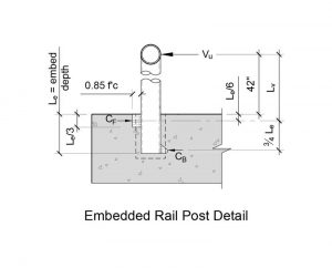
With the embedded rail post configuration, the horizontal rail loading is resisted by a shear couple in the implanted portion (Figure 4). Engineers often struggle with, and the industry provides little guidance for, the calculation of the imposed shear load on the concrete. One methodology used by the authors was developed by the Precast Concrete Institute (PCI) and is described in a PCI Journal article authored by Charles H. Raths in 1974. In this article, a methodology is offered for determining the distance between and position of the embedded shear couple (Figure 4). Once the shear force (CF) at the top of the embedment is determined, provisions in Chapter 17 can be used to determine if the surrounding concrete can resist the imposed shear force.
Concerns persist
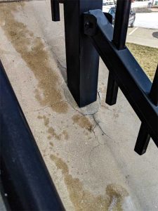
Some rail post anchorage configurations are simply not buildable if they are to accommodate all the various construction tolerances that need to be considered. For example, design of a rail post set in a concrete curb needs to accommodate railing setting tolerances (typically fixed by the manufacturer), reinforcement steel placement tolerances, and cover requirements (ACI 117, Specification for Tolerances for Concrete Construction and Materials), post edge distances (determined by design), and deviation of formed surfaces (ACI 117). A 200-mm (8-in.) wide curb is too narrow to accommodate a 100-mm (4-in.) wide embedded hole, or provide enough edge distance for an anchored base plate.
Similarly, thin concrete balconies also present issues if the post anchorage is not coordinated with reinforcement steel location and slab thickness. Figure 5 depicts an embedded rail post with a 150-mm (6-in.) edge distance (dimensioned from the slab edge to center of the rail post). Considering a preferred edge bar placement at the top location (right before the bend radius), a clearance of 20 mm (¾ in.) remains to account for construction tolerances. Moving the railing post closer to the slab edge would require the relocation of the edge bar or complete elimination of the edge reinforcement all together, but the removal would decrease the concrete breakout capacity.
Post pockets should not explode
 [7]
[7]This is, unfortunately, quite common. The concrete around a rail post pocket cracks, then spalls, quite spectacularly in some cases (Figure 1), creating falling hazards and rendering the post connection worthless. Not all post pockets fail this way. In some cases, the grout within the post pocket just simply weathers or turns to rubble (Figure 6).
The detail is deceptively simple: Set the post into a hole sleeved or core-drilled into the concrete and then fill the hole with grout.
As explained, the ‘explosion,’ or expansion of the contents of the pocket, can crack and spall the surrounding concrete, and sometimes thrust the rail post out of the pocket (Figure 7). There are three general mechanisms by which this expansion can occur:
- use of expansive grout in a wet environment;
- freezing and expansion of water in the pore structure of the grout; and
- corrosion of embedded metal, such as reinforcement steel, post sleeve, or the post itself.
All three mechanisms result from the use of inappropriate grout, and it is common for all three to occur within the same pocket. Exposure to the chlorides from de-icing agents and marine environments can significantly exacerbate the problem. In the authors’ view, a lot has been written about ‘non-shrink’ grout and its use for setting rail posts and stone cladding anchorage, yet it continues to be used largely because many of these products are marketed as being appropriate for outdoor use. Though the great product may be advertised for outdoor use there are several conditions listed in the fine print that must be met, and above all, the grout must not become wet—a highly suspect requirement for a material intended for the outdoors. If compliance with ASTM C1107, Standard Specification For Packaged Dry, Hydraulic-Cement Grout (Nonshrink), is specified, it should be with the caveat that the grout be demonstrably appropriate for outdoor, exposed, wet, and freeze-thaw conditions.
 [8]
[8]Non-shrink grout, as the name implies, typically incorporates shrinkage compensators to offset the normal dry shrinkage of cementitious grout during initial cure. Gypsum or hydrated calcium sulfate is often used as an expansive additive (or in some cases as the primary binder) to balance the shrinkage of the grout during curing, thereby making it non-shrinkable. Gypsum is mildly water soluble and tends to be unstable under prolonged exposure to moisture. The transformation of the sulfate mineral to a chemical structure with higher water content results in volume instability of the grout, thus creating an expansive force. Gypsum can also re-crystalize on drying, but in a weaker, less-compact form, and causes expansion. Over time, this cycling turns the grout into rubble. The problem worsens in freeze-thaw environments where water penetrates the grout and freezes, providing another expansion mechanism. Worse still, with gypsum in the pore solution, the pH is approximately neutral and not high enough to provide passive resistance to the corrosion of the embedded steel, another expansion mechanism. Even a small amount of inappropriate grout can be problematic, as shown in Figure 8 where not all of the material had been removed from a post pocket. The small amount left at the bottom of the pocket expanded and blew out the side of the wall.
Absolute avoidance of gypsum is impossible, as it naturally occurs in trace amounts in Portland cement and some mix aggregates. Even though the product literature may say “no added gypsum,” it is not necessarily gypsum-free (it should be noted ASTM C1107 does not preclude grouts with added gypsum). Cementitious grouts without added gypsum and tolerable to wet environments and freeze-thaw cycles are available. Epoxy-based grouts are effective and qualify as non-shrink, but can also be relatively expensive. The designer should decide whether non-shrink grout is really needed for the application. Shrinkage cracking within the grout is unacceptable but avoidable if it is properly mixed and cured. Many grouts are very specific about the degree of mixing and the required amount of water. It is recommended to stick with a proven, commercially available product, and avoid mixing and matching grouts, even from the same manufacturer.
Taking measures to reduce the exposure of the grout to moisture is also desirable. It is advisable to fully fill the post holes so water cannot pond (and freeze and thaw) in incompletely filled post holes. Crowning the grout to shed water is an option, as is installing a sealant bead around the base of the post to cover the grout. Sealant, however, is fallible and a regular maintenance item.
| When aluminum base plates have welded attachment flanges, or are to be welded to the post, the welding process reduces the allowable strength and may not be structurally adequate to transfer loads from the post to the plate.
Additionally, aluminum railings should be kept from contact with cementitious materials or dissimilar metals by the use of appropriate separation materials or specified coatings, such as a heavy-bodied bituminous paint, methacrylate lacquer, zinc chromate, or other coatings to prevent an aluminum-concrete reaction or an electrolytic action between aluminum and dissimilar metals. The design team needs to run the numbers and check compatibility of the specified materials.. |
Most railing systems are hollow, and condensation within the system should be weeped out at the post base. The weeps should be set such that the post base does not hold water. A pourable sealer can be used within the post to fill the hollow portion of the post up to the level of the weep. Some railing systems have condensation sleeves or diverters.
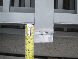
Did we just hit steel?
 [9]
[9]Most railing systems are not field-adjustable. Therefore, coordinating the rail post anchorage locations with other embedded items becomes extremely important. Installing sleeves for post pockets prior to pouring the concrete has the advantage of avoiding interference with other embedded items and avoiding the messy core drilling step. However, the locations of the rail posts need to be known early in the project, well before concrete placement. The railing and reinforcement installers and concrete subcontractor all need to be involved with coordinating the sleeve locations. Any errors in locating the sleeves lead to core drilling or expensive alterations of the railing system.
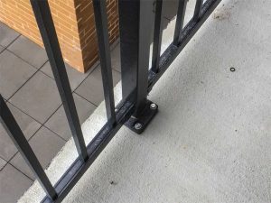
Core drilling post pockets or drilling for post-installed anchors is generally favored over sleeve or embed installation as it gives the railing installer flexibility about post location, is cheaper, and eliminates the pre-pour installation processes. However, lack of coordination of anchorage locations can lead to interference with the embedded items. Further, field modifications made to accommodate the interference can be problematic. Installed anchorages can conceal a multitude of sins, such as severed steel reinforcement, shortened rail post ends, and cut post-installed anchors. On one project that was investigated by the authors, reinforcement was hit on nearly every post hole, with the installer opting to either sever the steel or cut off the end of the post (Figure 9), shortening the post, and reducing the embedment, thereby weakening the anchorage. Resolving the issue involved:
- removal of the railing assemblies;
- cleaning out the (inappropriate) grout;
- chipping out the concrete at each post location;
- installation of supplemental reinforcing steel;
- placement of new concrete; and
- installing base plates on each post (Figure 10).
 [10]
[10]This situation can be avoided by taking the extra step to specifically require the coordination of rail post locations with the embedded items prior to casting concrete. Shifting and adjusting rebar and conduit locations can be done with much less effort than repairing it after the concrete has been placed.
Recommendations
Rail post anchorages need to be designed; they cannot simply be selected, or worse, ignored. Questions to be asked in the design phase include:
- are there proper load paths to the different supporting structural elements;
- can the structural element support the proposed rail post base reactions;
- is the edge distance adequate;
- can all construction tolerances be accommodated;
- if the design is delegated, have all the requirements been properly conveyed to the delegated designer; and
- has the delegated design been properly checked by the project’s EOR?
 [11]
[11]It is best to not use gypsum-based grout in an exterior application. The specifications should preclude grouts with gypsum-based binder. A product may be unsuitable for outdoor use if it cannot get wet. Many materials meet the non-shrink criteria and are suitable for outdoor, freeze-thaw environments.
Lastly, it is recommended to predetermine post anchor locations and coordinate the locations with embedded items. It is pertinent to note railing system installation is an integrated process requiring input from and coordination of more than one party.
- [Image]: https://www.constructionspecifier.com/wp-content/uploads/2019/06/bigstock-Stone-Steps-And-Metal-Rails-T-247256554.jpg
- [Image]: https://www.constructionspecifier.com/wp-content/uploads/2019/06/figure-1.jpg
- [Image]: https://www.constructionspecifier.com/wp-content/uploads/2019/06/Photo-04-concrete.jpg
- [Image]: https://www.constructionspecifier.com/wp-content/uploads/2019/06/Photo-05-concrete.jpg
- [Image]: https://www.constructionspecifier.com/wp-content/uploads/2019/06/Figure-1-concrete.jpg
- [Image]: https://www.constructionspecifier.com/wp-content/uploads/2019/06/Figure-2-concrete.jpg
- [Image]: https://www.constructionspecifier.com/wp-content/uploads/2019/06/Photo-06-concrete.jpg
- [Image]: https://www.constructionspecifier.com/wp-content/uploads/2019/06/Photo-07-concrete.jpg
- [Image]: https://www.constructionspecifier.com/wp-content/uploads/2019/06/Photo-08-concrete.jpg
- [Image]: https://www.constructionspecifier.com/wp-content/uploads/2019/06/Photo-09-concrete.jpg
- [Image]: https://www.constructionspecifier.com/wp-content/uploads/2019/06/Photo-10-concrete.jpg
- blipinski@rrj.com: mailto:blipinski@rrj.com
- mlwagner@rrj.com: mailto:mlwagner@rrj.com
Source URL: https://www.constructionspecifier.com/design-considerations-for-rail-post-anchorage-into-concrete/