

by Bradford Douglas, PE, and Jason Smart, PE
Designing for life safety is complex and multifaceted, and fire-related issues comprise a large portion of model codes. For nearly 15 years, a mechanics-based design method has been used in the United States to estimate the capacity of exposed wood members using basic wood engineering mechanics.
This mechanics-based design method first appeared in the 1999 version of Technical Report (TR) 10, Calculating the Fire Resistance of Exposed Wood Members (TR 10). This method was then incorporated into new design procedures of the 2001 National Design Specification (NDS) for Wood Construction. These procedures were later adopted into the model building codes through reference to the NDS for calculating fire resistance of wood members. The procedures have been used extensively for design of large, exposed wood members, but are now also beginning to be employed for estimating structural fire resistance of smaller exposed wood members.
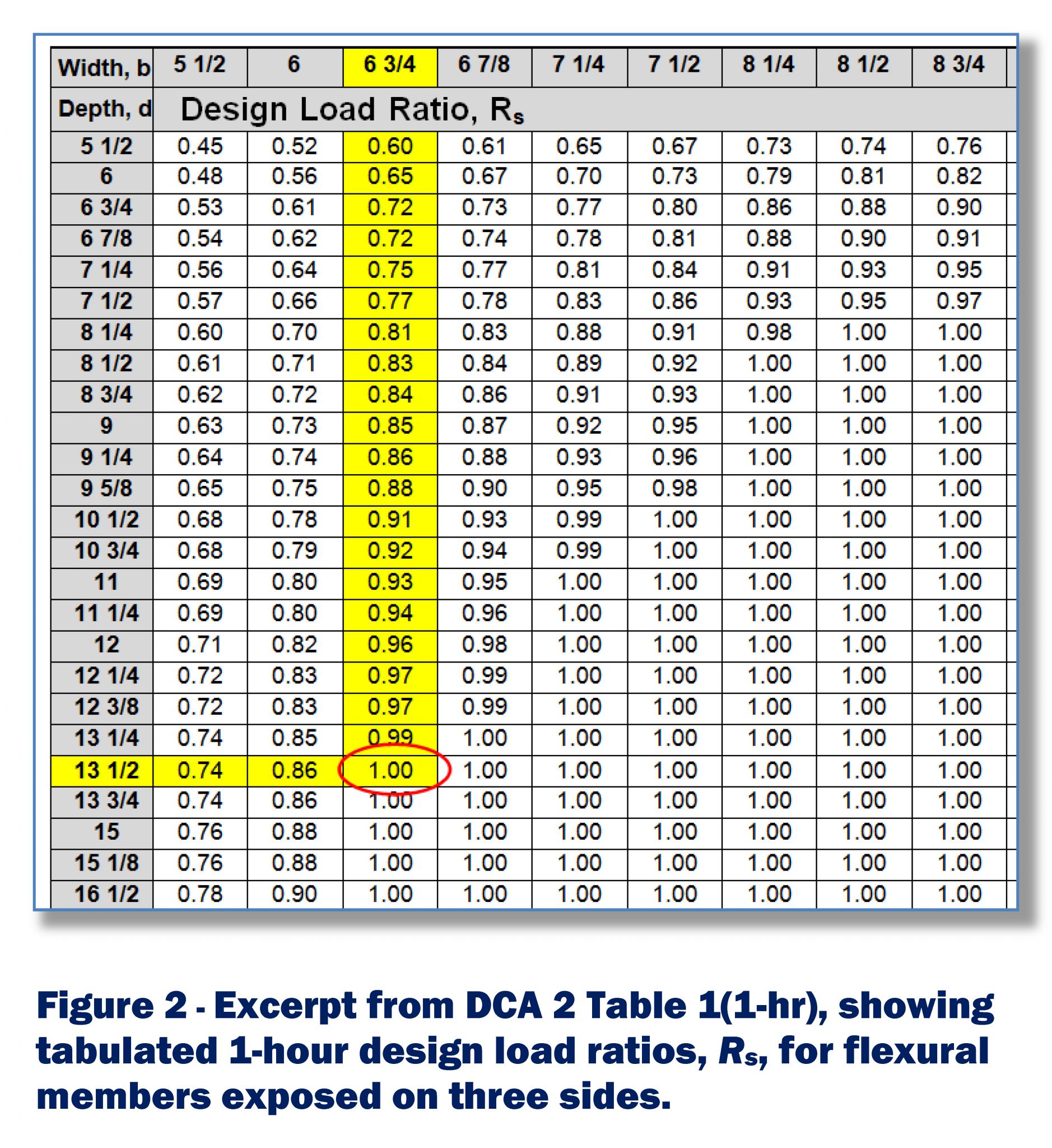
![Excerpt from Design for Code Acceptance (DCA) 2, Design of Fire-resistive Exposed Wood Members, Table 1 (one-hr). This shows tabulated one-hour design load ratios, Rs, for flexural members exposed on three sides. [CREDIT] Data courtesy American Wood Council](http://www.constructionspecifier.com/wp-content/uploads/2014/06/Constr-Specfr-Douglas-Smart-Fire-140506_Page_6.jpg)
Fire resistance is a measure of the length of time an assembly or structural element can sustain a given load when subjected to a standardized fire exposure condition. Fire resistance of wood members and assemblies may be established by any one of five means listed in IBC Section 703.3, “Alternative methods for determining fire resistance.” The most common methods are tested assemblies and calculated fire resistance.
Fire design of exposed wood members
The fire resistance of exposed wood members, including lumber, glued-laminated (glulam) timber, and structural composite lumber (SCL), may be calculated using provisions of NDS. This allowable stress design approach is referenced in IBC Section 722, “Calculated Fire Resistance.” The design procedure allows calculation of the capacity of exposed wood members using basic engineering mechanics.
Actual mechanical and physical properties of the wood are used, with member capacity directly calculated for a given period—up to two hours. Section properties are computed assuming an effective char rate (i.e. ?eff) at a given time (i.e. t). Reductions of strength and stiffness of wood directly adjacent to the char layer are addressed by accelerating the char rate by 20 percent. Average member strength properties are approximated from existing accepted procedures used to calculate design properties. Finally, wood members are designed using accepted engineering procedures found in NDS for allowable stress design. (The design procedures presented in NDS Chapter 16 are not intended to be used for the design and retrofit of structures after a fire.)
For sawn lumber, glulam, and SCL, the nominal char rate (i.e. ?n) is typically assumed to be 38 mm/hour (1.5 in./hour). For a given time in hours, the effective char rate is then:
?_(eff=) 1.8/t^0.187 in./hour
To calculate section properties of wood members, the effective char layer thickness (i.e. aeff), for structural calculations is computed as:
a_(eff=) 1.8t^0.813 in.
The 2012 and earlier versions of IBC have also contained an empirical calculation method for estimating the structural fire resistance of wood beams and columns exposed to a standard fire exposure for up to one hour. However, this empirical method has been removed from the 2015 IBC in favor of provisions contained within NDS Chapter 16 that are much broader in application and leave less room for design error.
Basis for NDS chapter 16 approach
AWC’s TR 10 contains full details of the NDS method as well as design examples.1 TR 10 was recently revised to incorporate a new section that supports the use of the design method with smaller dimension sizes associated with lumber joist floor assemblies. It also has revised design examples to match the 2012 NDS.
The revised design tables in Appendix A allow more accurate calculation of fire resistance of columns with any slenderness ratio. They also eliminate tabulation of special cases that can be misapplied, such as:
- deleted beams exposed on four sides that are assumed to be fully braced throughout the fire rating;
- columns only exposed on three sides, but assumed to be unbraced; and
- tension members that do not resist flexure due to member dead load.
Finally, a new Appendix B that calculates the fire resistance of single-span lumber joists for any design stress ratio when joists are exposed on three sides and braced on the top edge was incorporated.
Simplified approach
AWC’s Design for Code Acceptance (DCA) 2, Design of Fire-resistive Exposed Wood Members has been revised to replace the empirical design equations currently in the 2012 IBC with simplified design information developed in accordance with the code-approved NDS fire design procedure for exposed wood members. The tables and examples have been rewritten for consistency with the approach outlined in the 2012 NDS and TR 10.
For beams and columns stressed in one principal direction, simplifications can be made to allow creation of load ratio tables. These tables can then be used to determine the structural design load ratio at which the member has sufficient capacity for a given fire resistance time. Tables in DCA 2 give load ratios corresponding to one-hour, 1.5-hour, and two-hour fire resistance ratings for specified member dimensions.
All tabulated load ratios apply to standard reference conditions where the load duration factor, wet service factor, and temperature factor equal 1.0 (CD=1.0; CM=1.0; Ct=1.0). For more complex calculations where stress interactions must be considered, or where standard reference conditions do not apply, designers should use the provisions outlined in TR 10, along with the appropriate NDS provisions.
Flexural members
Design load ratios (i.e. Rs) for fire design of flexural members for various beam sizes are tabulated in DCA 2 tables for one-hour, 1.5-hour, and two-hour fire resistance ratings. The Rs values given in these tables apply to three-sided exposure in which the beam’s top edge is protected from fire exposure (e.g. protected by the underside of a floor or roof). These tabulated values apply to flexural members loaded in bending about one axis only, and are continuously laterally supported along the compression edge. The dimension ‘d’ is the actual cross-sectional dimension measured in the direction normal to the axis about which bending occurs, and is not necessarily greater than ‘b’ (Figure 1).
To use the DCA 2 tables, the designer only needs to know the required fire resistance rating (FRR), the structural load ratio (Rs), and the beam dimensions. For example, when a beam is exposed on three sides and is protected by a floor deck bracing the compression edge, it is required to have a one-hour FRR. When the design professional wants to use a 152.4 x 330.2-mm (6 ¾ x 13 ½-in.) beam being loaded in bending about the strong axis, DCA 2 Table 1 (one-hour) shows a 152.4 x 330.2-mm beam would calculate to have a one-hour fire resistance rating if loaded to its full design load (Rs=1).
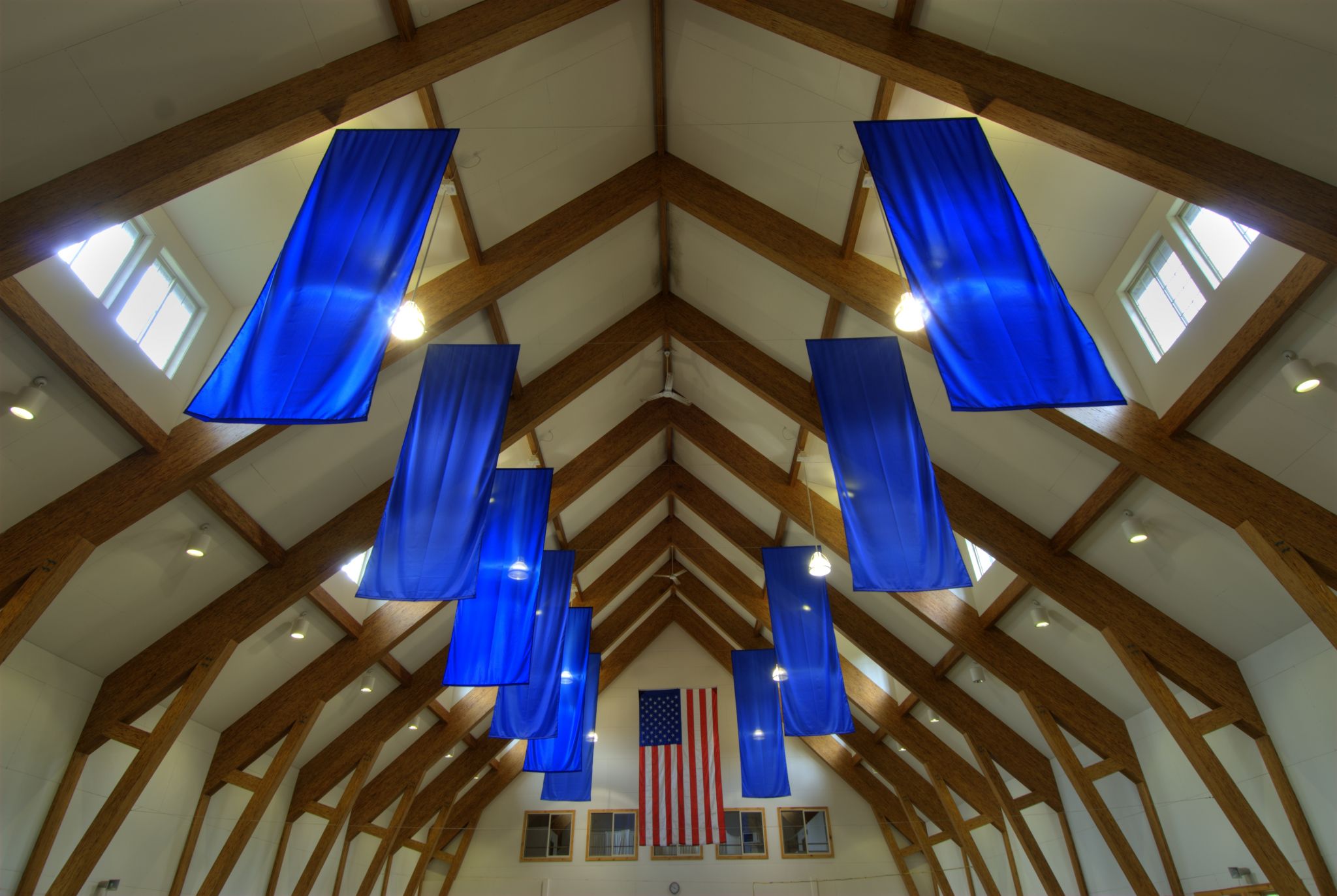
![The entrance of the Rocky Mountain Elk Foundation building. [CREDIT] Photo courtesy Structurlam/OZ Architects](http://www.constructionspecifier.com/wp-content/uploads/2014/06/RMEF-057.jpg)

Compression members
Design load ratios, Rs, for fire design of columns are calculated as the product of two ratios, Rs1 and Rs2. Values of Rs1 and Rs2 for various column sizes are tabulated in DCA 2 for one-hour, 1.5-hour, and two-hour fire resistance ratings. For cases in which the product of Rs1 and Rs2 is greater than 1.0, Rs should be taken as 1.0. These tables apply to cases in which all four sides are exposed to the fire; however, values calculated using these design load ratios may be conservatively applied when one or more sides of the column are protected. Both‘d’ and ‘b’ represent the dry dressed cross-sectional column dimensions. The dimension ‘d’ is the actual dimension measured in the direction perpendicular to the axis about which buckling is being considered, and is not necessarily greater than ‘b’ (Figure 2). The designer should consider buckling about both axes and use the lesser design value.
The tabulated Rs1 values are calculated based on a square column cross-section having dimensions ‘d’ by ‘d,’ and therefore must be multiplied by Rs2 for any column that is not square. Where ‘b’ is less than ‘d,’ Rs2 will be less than 1.0; and where ‘b’ is greater than ‘d,’ Rs2 will be greater than 1.0. The Rs1 values are derived using the more conservative value of the parameter ‘c’ from equation 3.7-1 of the NDS (for long columns, c=0.9 results in lower Rs1 values; for short columns, c=0.8 results in lower Rs1 values). This allows the design load ratios to be used with sawn lumber, structural glulam, or SCL. The Rs1 values are also based on the assumption that Emin’/Fc*= 350. As a result, the design load ratios (Rs) may conservatively be used for all species and grades where the ratio of Emin’ to Fc* is greater than or equal to 350.
 To use the tables, the designer only needs to know:
- required fire resistance rating;
- structural load ratio;
- column dimensions;
- unbraced length of the column; and
- end support conditions.
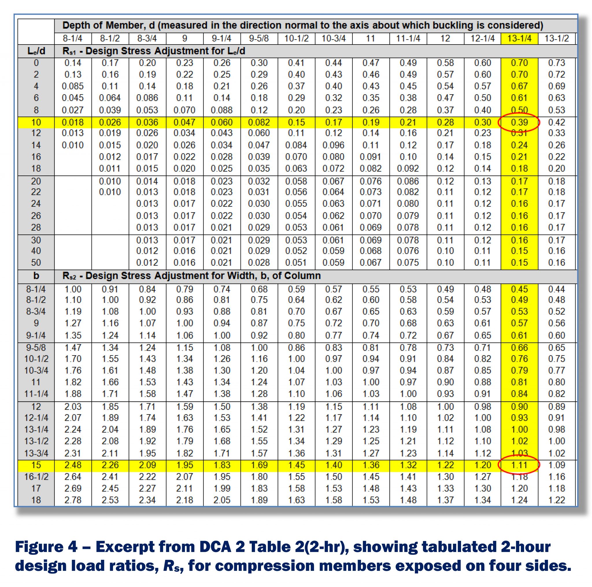
For example, in a case where an exposed column is required to have a two-hour FRR, the designer may want to use a nominal 14×16 column with actual dry dimensions of 330 x 381 mm (13 ¼ x 15 in.). The column will have an unbraced length of 3.35 m (11 ft) in both directions, and can conservatively be assumed to have pinned end conditions on each end of the column (Ke=1.0).
Since the unbraced length is the same in both directions, buckling would tend to be about the 13¼-in. dimension. The effective length (i.e. Le) would be 3352 mm (132 in.) and the Le/d ratio would be 10. From DCA 2 Table 2 (two-hour), a square column that is 13¼ x 13¼ in. with Le/d=10 would have an Rs1=0.39. A 13¼ x 15-in. column buckling about the 13¼ in. dimension would have an Rs2=1.11. Therefore, the 13¼ x 15-in. column would calculate to have a two-hour fire resistance rating when loaded to 43 percent or less of its full design load (Rs = [Rs1][Rs2] = [0.39][1.11] = 0.43).
Timber decking
DCA 2 also provides tabulated design load ratios (Rs) for various decking types and thicknesses, corresponding to one-hour, 1.5-hour, and two-hour fire resistance ratings. The dimensions ‘b’ and ‘d’ given in these tables are the actual dry dressed dimensions of each individual member. The Rs values given in DCA 2 Table 3.1 are applicable to butt-joint timber decking fully exposed on one face and partially exposed on the sides, in accordance with NDS Section 16.2.5.
The Rsvalues given in DCA 2 Table 3.2 are applicable to double and single tongue-and-groove decking exposed only on one face. These calculation procedures do not address thermal separation.
 To use the tables, the designer only needs to know the required fire-resistance rating, the structural load ratio (Rs) and the decking type and dimensions. For example, a timber deck is required to have a 1.5-hour FRR, and the designer wants to use 4x tongue-and-groove decking. From DCA 2 Table 3.2, the nominal 4x tongue and groove decking (76.2 mm [3½ in.] actual thickness) would calculate to have a 1.5-hour fire resistance rating if loaded to 23 percent or less of its full design load (Rs=0.23).
Connections
Where a specified fire resistance rating is required, Section 16.3 of the NDS requires connectors and fasteners be protected from fire exposure. This protection can be achieved by any of the following:
- wood members having dimensions sufficient to prevent the char front from reaching the connectors and fasteners for the duration of the required fire-resistance rating time—the char front can be calculated as: a=1.5t^0.813 in.;
- fire-rated gypsum board having a finish rating greater than or equal to the required fire-resistance rating; and
- any approved coating having a fire rating greater than or equal to the required fire resistance rating time.
Conclusion
Structural fire design provisions have been incorporated in Chapter 16 of NDS, which is referenced in Section 722.1 of the 2012 IBC as a method of calculating fire resistance of exposed wood members. A comprehensive discussion of this mechanics-based design procedure can be found in Technical Report No. 10, while DCA 2 provides a simplified design aid of this code-approved fire design procedure for several typical applications with exposed wood members. 2
Notes
1 For more information, TR 10, Calculating the Fire Resistance of Exposed Wood Members, is available at www.awc.org/pdf/TR10.pdf.
2 Additional information on building code requirements for wood can be found in the American Wood Council’s Code Conforming Wood Design documents, available at www.awc.org/codes/ccwdindex.php.
Brad Douglas, PE, joined the American Wood Council (AWC) in 1986, and serves as its vice president of engineering. Douglas directs a program aimed at developing state-of-the-art engineering data, technology, and standards on structural wood products, systems, and assemblies for use by design professionals and building officials to assure safe and efficient design and use of wood. He is a graduate of Virginia Tech. Douglas can be contacted at bdouglas@awc.org.
Jason Smart, PE, joined AWC in 2013 and is manager of engineering technology. Smart focuses on development and support for new and emerging technologies and related changes to design and model building code standards. He is a graduate of Virginia Tech with degrees in civil engineering, wood science and forest products, and timber engineering. He can be reached at jsmart@awc.org.


Even though most codes say a 2 x 4 piece of blocking is allowed in a 1 hr. wall. I can not find anything that says it has been tested as such. I simply want to know where I can find data that shows any 2″ (nominal) piece of blocking (or a ledger board) has that rating.