

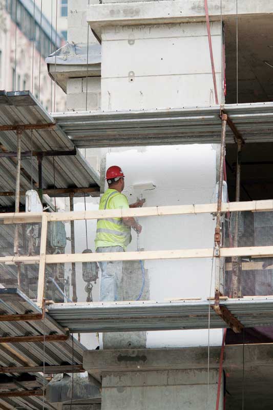
Photo courtesy Dupont
Figures 6 and 7 show WUFI simulation results for diffusion and air infiltration summer condensation potential. The exterior climate and interior conditions for these examples were selected to simulate a scenario with a large diffusion driving force—such as Houston, Texas, with a Zone 2A exterior climate and low internal moisture conditions (45 percent ± 15 percent RH and 21 C ± 1 C [69.8 F ± 1.8 F]).
The two walls in these examples are hybrid/split insulation steel-framed walls with brick cladding, vapor-permeable air and water barriers (>25 perms), and no interior vapor retarders. Two ci materials were simulated to estimate the impact of vapor permeability of exterior layers on diffusion condensation potential:
- 25.4-mm (1-in.) XPS (0.8 perm-in.); and
- 31.75-mm (1.25-in.) mineral wool (>50 perm-in.).
The ci thickness was based on 2012 IECC requirements for Climate Zone 2A (R-13 + R-5 ci).
The simulation results in Figure 6 show practically no condensation potential from vapor diffusion—including inward solar-driven moisture—for either of the two wall assemblies. Even when exterior layers are vapor-permeable (e.g. mineral wool wall assembly), the amount of moisture from vapor diffusion is only very slightly higher than for the wall with XPS vapor-impermeable exterior layer wall, and remains below the equilibrium moisture content of the gypsum board sheathing throughout the year. The wall assemblies in these examples do not contain an interior vapor barrier/retarder, which is not required by code in this climate; drying to the interior was allowed during the summer months.
However, infiltration of warm, moisture-loaded exterior air which can transport significantly more moisture than vapor diffusion could lead to condensation within the interior sheathing as shown by the WUFI simulation results in Figure 7. These examples show the temperature of the condensation layer (interior sheathing) during summer months is below the dewpoint temperature of exterior air for both wall assemblies.
Under these conditions, condensation could occur if air infiltration reaches the condensation plane. While the number of hours of potential condensation for the year can be estimated, it depends on both interior moisture loads and exterior temperatures. Also, since air leakage is unpredictable, it is difficult to define failure criteria for the related condensation potential.
Based on WUFI simulations and field experiments, it is this author’s opinion that problems often attributed to solar-driven moisture, and associated with moisture storage cladding such as brick or stucco, are most likely due to air infiltration, not vapor diffusion. Poor air barrier continuity could contribute to air leakage condensation, and improper wall design—such as use of vapor-impermeable materials on the interior side of the wall in warm climates—could further aggravate the consequences of air leakage condensation. (To read more, see Research Report-1011, “Evaluation of Cladding and Water-resistive Barrier Performance in Hot-Humid Climates Using a Real-weather, Real-time Test Facility,” by Theresa Weston.)
The importance of a continuous air barrier in every climate cannot be emphasized enough. The impact of air leakage on moisture control can sometimes be overlooked if the justification for an air barrier focuses strictly on energy savings, which are lower in warmer climates than cold and mixed climates. However, anyone involved with remediation due to moisture problems understands that the time and cost involved outweigh any upfront expenses to properly implement an air barrier design, construction, and verification program.
Simulated drying rates
WUFI simulations could be used to compare drying rates for different climate conditions and wall assembly design following a wetting event. Drying is very important for long-term durability. Good enclosure design minimizes the risk of wetting, but moisture intrusion can never be completely avoided, and drying potential must always be considered. If a wall is able to dry, it may experience some wetting without long-term durability risks.
The WUFI model has the ability to compare drying rates after a wetting event, which is a relative way to compare potential long-term durability of different design options for given conditions. The following examples illustrate the dependence of drying rates on wall assembly design, material choices, and ventilation behind exterior cladding.
Impact of wall assembly design on drying rates
The drying rates for three wall assembly design options—traditional, split insulation, and exterior insulation walls—are compared here.
The various WUFI simulations were performed for Chicago’s Zone 5A exterior climate and medium interior moisture conditions (50 percent ± 10 percent RH and 21 C ± 1 C [69.8 F ± 1.8 F]). The characteristics of the three walls were:
- Traditional wall: interior gypsum board, 1-perm vapor retarder (per 2009/2012 IBC requirement, Climate Zone 5A), 2×6 steel-stud cavity with 140-mm (5.5-in.) fiberglass batt insulation, exterior gypsum board sheathing, >25 perms air and water barrier, air space, and exterior cladding.
- Hybrid/split insulation wall: interior gypsum board, 1-perm vapor retarder, 2×4 steel-stud cavity with 89-mm (3.5-in.) fiberglass batt insulation, exterior gypsum board sheathing, >25 perms air and water barrier, 38-mm (1.5-in.) XPS exterior insulation (for R-13 +R 7.5 ci, per 2012 IECC), air space, and exterior cladding.
- Exterior insulation wall: interior gypsum board, 2×4 steel stud cavity with no insulation, exterior gypsum board, >25 perms air and water barrier, 76-mm (3-in.) XPS exterior insulation, air space, and exterior cladding.
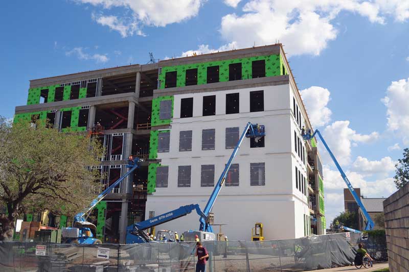
Photo © Corey Ball. Photo courtesy WPL Tyvek
To compare the drying rates for the three wall design options, the simulations were started with elevated moisture content in the exterior sheathing (e.g. 250 kg/m3[15.6 lb/cf]) for all three walls, and the drying curves of the wetted layer were observed. (Another way to simulate wetting in WUFI analysis is by allowing a certain fraction of rain to penetrate the wall assembly and to compare the drying rates, but this is also a relative analysis since it is impossible to predict how much, and when, rain will infiltrate.) WUFI simulations were performed for a three-year period, but only the first is plotted in Figure 8 which shows the comparative drying curves for the three wall assemblies.
The graphs in Figure 8 show the different drying rates for the three wall assemblies. The exterior insulation wall design dries the quickest, taking less than 500 hours to reduce the moisture content from 250 kg/m3 to equilibrium water content levels (e.g. 6.19 kg/m3[0.39 lb/cf]). The diffusion drying for the exterior insulation wall is less critical because the stud cavity is part of the interior conditioned space and the HVAC-aided drying occurs quickly. The traditional wall design also dries fast, taking less than 800 hours to reduce the moisture content from 250 kg/m3 to equilibrium levels.
The hybrid/split insulation wall assembly dries the slowest; even after a full year, the moisture content in the exterior gypsum board sheathing has not reached equilibrium values. The drying analysis should be interpreted as a comparison of relative drying potential since it is difficult to predict when and how much a wall will be wetted. In this example, the simulation began with very high moisture levels in exterior gypsum board to emphasize the differences in the drying rates of wall assemblies. Hopefully, such high moisture levels are very rarely experienced in practice.
The slow drying rates for the hybrid/split insulation wall in this example should certainly be of concern, since hybrid wall design is becoming the most common steel-framed wall construction to meet prescriptive energy code requirements, and XPS exterior insulation is often the default choice of continuous insulation.

