

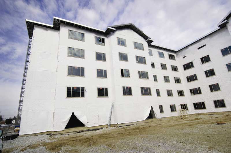
Photo courtesy Dupont
Impact of materials choices on drying rates
The slower drying rates for the hybrid/split insulation wall assembly in Figure 8 are partly attributed to the inherent lower drying rates of energy-efficient assemblies (drying needs heat, and there is less heat flow through energy efficient assemblies). However, drying rates are significantly impacted by the choice of materials.
Diffusion drying for the hybrid wall assembly in this example in Figure 8 should occur almost exclusively to the outside, which is the preferential diffusion direction in climate Zone 5A. This wall was also simulated with an interior vapor retarder (1-perm, required by 2012 IBC), so there is little to no drying potential to the inside. Further, the exterior insulation was XPS, with a vapor permeance of 0.8 perm-in., which means the material served as an unintentional vapor retarder. In addition to placing the XPS on the ‘wrong’ side of the enclosure (the cold side), this wall assembly contains two vapor retarders: the intentional one to the inside required by code, and the additional XPS to the outside. Having double or multiple vapor retarders in a wall assembly is not a good practice for moisture management.
‘Diffusion-open’ pathways to the exterior (the preferred diffusion direction for Climate Zone 5A) are important for drying, as demonstrated by the following two examples. A vapor-permeable material provides a diffusion-open pathway, which favors diffusion drying. By comparison, a vapor barrier or retarder is diffusion-closed.
The first example in Figure 9 compares the drying rates for two hybrid/split insulation wall assemblies, one with vapor-impermeable XPS exterior insulation (38-mm [1.5-in.], 0.8 perms-in.), the other with vapor-permeable mineral wool exterior board insulation (50 mm [2 in.], >50 perms-in.). The ci thickness was based on 2012 IECC requirements for Zone 5A (R-13 + R-7.5 ci). The second example (Figure 10), compares the drying rates for two hybrid/split insulation wall assemblies with mineral wool exterior insulation (50 mm, >50 perms-in.), one with vapor-permeable WRB membrane (>25 perms), and the other with vapor-impermeable WRB (<0.1 perms). Both graphs also include the drying rates of a traditional wall design, for comparison purposes.
Both examples show that diffusion open pathways to the outside significantly increase the split insulation wall assembly’s drying rates. Even though the split insulation wall dries inherently slower than the traditional wall (the traditional wall is included in both graphs for comparison purposes), opening the diffusion drying pathway to the outside brings the split insulation wall assembly within acceptable drying rates. These examples demonstrate energy-efficient wall assemblies can be designed with low risk for long-term durability with the correct choice of materials.
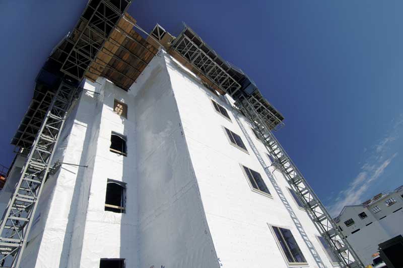
Photo courtesy Dupont
Effect of ventilation on drying rates
In some situations, diffusion is the only practical mechanism available for drying,5 and WUFI simulations demonstrate its importance on the drying rates of different wall assemblies. However, drying rates could be further improved with ventilation behind cladding.
WUFI simulations in this section compare the drying rates for two hybrid/split insulation wall assemblies similar in all regards except for ventilation behind cladding. Both walls have diffusion-open pathways toward the outside to allow diffusion drying, but one is vented (i.e. 50 air changes per hour [ach]), and the other has no venting behind cladding (i.e. 0 ach).
Figure 11 shows the impact of venting on the drying rates for Chicago’s exterior climate Zone 5A, and medium interior moisture conditions (50 percent ± 10 percent RH and 21 C ± 1 C [69.8 F ± 1.8 F]).
A recent study by John Straube, PhD, and building science research engineer Graham Finch demonstrates the importance of vented cladding on the drying rates of wall assemblies, and compares the moisture content predicted by WUFI simulations with the experimental MC in the exterior sheathing. The study found the measured MC in the exterior sheathing was generally lower than the content estimated through WUFI simulations, even at high ventilation rates behind the cladding (100 ach).
Based on the field results, the authors concluded when ventilation behind cladding is not included in WUFI simulations, MC could be overestimated by as much as 15 percent. All WUFI simulation examples in this paper used 50 ach ventilation rate (except for the example in Figure 11 which was performed with 0 ach).
Conclusions
New energy-efficiency measures often require changes in traditional building envelope design, with the hybrid/split insulation wall design becoming the simplest steel-framed wall assembly to meet the prescriptive energy code requirements. The slow drying rates for the hybrid wall design are of special concern. While the more energy-efficient split insulation wall design has inherently slower drying rates (because drying needs heat and there is less heat flow through energy-efficient assemblies), the long-term durability risks could be significantly reduced with the correct material choices.
The most concerning practice for split insulation wall design is the default choice of vapor-impermeable insulation materials as the exterior ci, which introduces an unintended (and second) vapor barrier/retarder in the wall assembly. While less common, use of other vapor-impermeable exterior layers (such as low-perm WRBs) is also an inappropriate practice. Such choices of materials could impact long-term durability risks by significantly reducing the diffusion drying rates of wall assemblies.
The practice of using dewpoint calculation as a design guide provides a false sense of security. This is because the dewpoint in most hybrid wall assemblies is located to the exterior of WRB layer, which indicates there is no diffusion condensation potential in these assemblies. However, as discussed throughout this article, the dewpoint calculation alone provides no information on other important moisture sources and how different assemblies manage incidental moisture instruction (e.g. drying rates following a wetting event).
There is less experience with the design and performance of split insulation wall assembly, and experimental data for long-term durability takes many years to develop. In the meantime, moisture analysis could be used to estimate the long-term durability risks for different climates and material choices.
This article provided examples of how WUFI moisture analysis could be employed to compare different design options. Even though the conclusions only apply to the specific conditions for which WUFI simulations were performed, the methodology could be applied to any system or climate to better understand the long term performance of different design options, and to help make the best design decisions.


Maria Spinu, PhD, CSI, LEED AP, received her doctorate in polymer science from Virginia Tech and has worked with DuPont for two decades. She currently leads the Building Innovations group’s building science and sustainability initiatives. Spinu is a member of the American Society of Heating, Refrigerating, and Air-conditioning Engineers 90.1 Committee and envelope subcommittee, and has authored 15 patents. She can be contacted at maria.spinu@usa.dupont.com.

