Designing brick veneer for loadbearing exterior walls
by Katie Daniel | September 19, 2017 2:15 pm
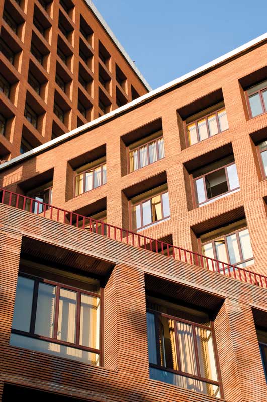 [1]
[1]by Michael Gurevich
Loadbearing walls with brick veneer and concrete masonry units (CMUs) were built as solid walls in the first half of the 20th century. Brick veneer and the CMU backup wall were bonded to a solid wall to carry the dead and live loads. In the second half of the century, a cavity wall system was introduced with an air space between the brick veneer and the CMU backup wall that was designed to carry the load. The insulation was located at the interior face of the CMU wall, and the brick veneer was completely separated from the loadbearing function.
In the 21st century, practices evolved further. Loadbearing wall systems are often modified by locating all insulation in the air space between the brick veneer and the CMU backup wall. Thus, the CMU backup wall is designed to carry the dead and live loads, and is located behind the insulation in the same environment as the interior space of the building, with a constant temperature of approximately 20 C (68 F). Brick veneer is thermally separated from the CMU backup wall, with its temperature dependent on the weather.
With this system, the CMU backup wall is constructed with the bond beam at the building perimeter located at every floor window head level. Continuous steel shelf angles are attached to the bond beam with through-bolts and back plate. Shelf angles are designed to carry the brick veneer, which should have a minimum bearing of 63.5 mm (2 ½ in.).
Masonry ties should project from the CMU horizontal joints and through the insulation board into the air space to receive the hook part of the masonry ties, which should be embedded into the horizontal joints of the brick veneer. The International Building Code (IBC) limits the vertical deviation between two parts of the tie to 31.75 mm (1 ¼ in.). Thus, the coursing of the CMU backup wall should match the coursing of the brick veneer. The vertical spacing of the masonry ties should not exceed 406 mm (16 in.).
Rigid, extruded polystyrene (XPS) insulation board should be installed continuously over the outside face of the CMU wall. This should be 406 mm wide (to be installed between the masonry ties) and 2438 mm (96 in.) long. All horizontal and vertical joints between the insulation boards should be sealed.
A vapor barrier should be installed over the outside face of the CMU backup wall (behind the insulation board). A liquid-applied, spray-on vapor barrier should seal around the masonry ties projecting from the CMU horizontal joints. A peel-and-stick membrane vapor barrier could be used, but it is labor-intensive to seal around the masonry ties with this barrier type.
Brick veneer should be installed with a running bond pattern, and with masonry ties anchoring it to the CMU backup wall. Brick Industry Association (BIA) recommends in Technical Note 28B, Brick Veneer/Steel Stud Walls, providing a 51-mm (2-in.) clear air space behind the brick veneer, with one exception. If the XPS insulation board with sealed horizontal and vertical joints is installed over the vapor barrier and the CMU backup wall, the air space could be reduced down to 25 mm (1 in.). The reason is the XPS insulation board is a closed-cell product and not sensitive to moisture. If moisture reaches the XPS insulation board, it will migrate over the board surface down to the weep holes and drain out from the wall system. IBC limits total size of the cavity to 114 mm (4 ½ in.) from the outside face of the CMU backup wall to the inside face of the brick veneer, to limit the unbraced length of the brick veneer ties. If the total size of the cavity exceeds the 114-mm limit, structural analysis of the brick veneer ties is required.
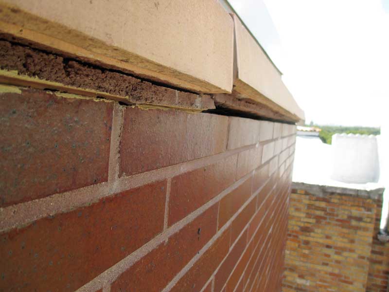 [2]
[2]Photos courtesy New York City Brickwork Design Center
Movements in the brick veneer
Brick veneer normally experiences moisture expansion and thermal expansion/contraction, which is absorbed by its expansion joints. (Expansion joints are used for clay brick masonry walls, which expand, and should be filled with compressible material. Concrete masonry, however, typically experiences contraction, and should be designed with the inclusion of control joints filled with premolded materials.) The horizontal expansion joints in the brick veneer should be located at the continuous steel shelf angles at every floor level.
Brick veneer at the typical apartment building wall is approximately 3 m (10 ft) high per floor, and the moisture expansion of this brick veneer could be calculated with the Brick Industry Association (BIA) formula:
0.0005 x L
= 0.0005 x 10 ft x 12 in.
= 0.06 in.
This is approximately 1.5 mm (1/16 in.) per floor.
The moisture expansion behavior of the clay brick depends primarily on the raw materials and secondarily on the firing temperatures—the specifics are beyond this article’s scope. Such expansion is an irreversible process, primarily taking place during the first months, but continuing at a much lower rate for several years.
In addition to moisture expansion, brick veneer undergoes thermal expansion. Walls with dark-colored brick and southern exposure could have temperatures at the brick face of approximately 57 to 60 C (135 to 140 F) in the summer. The winter temperature of the brick veneer could fall below the freezing point to –12 C (10 F) in other locations, such as New York City. The vertical thermal expansion of this brick veneer one floor high could be calculated with this BIA formula:
0.000004 x (Tmax − Tmin) x L
= 0.000004 x (140−10) x 10 ft x 12 in.
= 0.0624 in.
This is approximately 1.5 mm (1/16 in.) per floor.
The total maximum vertical expansion of 3-m high brick veneer (W) could be:
1/16 in. + 1/16 in.
= 1/8 in.
Brick veneer evenly expands up from the support at the continuous shelf angle located at every floor level, but the shelf angle moves down with the CMU bond beam to which the angle connects.
Vertical expansion joints in the brick veneer should be located at each side of the exterior corners within 1.5 m (5 ft) of the corner, and then at 7 m (25 ft) apart, in accordance with BIA recommendations. The most economical location of the brick veneer vertical expansion joints would be at the window jambs (with a continuous shelf angle located at each floor window head level), because there is a soft joint between the window frame and the brick veneer window jamb anyway. The expansion joint should be provided within the brick veneer spandrel panel only.
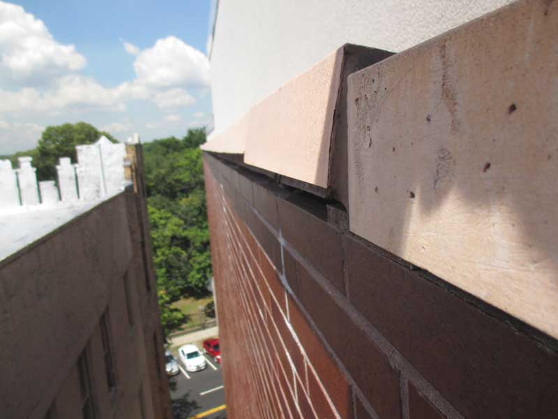 [3]
[3]Movements in the loadbearing CMU backup wall
Changes in moisture content and temperature cause expansion and contraction of concrete masonry walls. The magnitude of volume change depends on two factors—one an intrinsic property of the concrete masonry unit, and the other a changing condition of temperature fluctuation and moisture loss. The National Concrete Masonry Association (NCMA) publishes Technical Notes on concrete masonry technology, including NCMA TEK 10-2A on Movement Control, which has the following information:
Crack Control Coefficient
The Crack Control Coefficient (CCC) is an indicator of anticipated wall movement and is the key criteria for controlling cracking. Concrete masonry unit shortening per unit length is estimated by including the combined effects of movement due to drying shrinkage, carbonation shrinkage and contraction due to temperature change. The Crack Control Coefficient value itself is determined by summing the coefficients of these three properties for a specific [CMU]. It is a function of mix design and production/curing methods.
The total linear drying shrinkage is determined in accordance with Standard Test Method for Drying Shrinkage of Concrete Masonry Units and Related Units, ASTM C 426.
Carbonation shrinkage of the unit occurs over a long period of time and is the change in linear dimension per unit length resulting from carbonation (an irreversible reaction between cementitious materials and carbon dioxide in the atmosphere).
Contraction due to temperature decrease is determined by multiplying the thermal expansion/contraction coefficient for the CMU by a temperature change of [39 C] 70 F.
The CCC is the sum of the potential length change due to each of these three parameters and for typical CMU varies. This range corresponds to a [31 m] 100 ft long (or high) wall shortening, using the previously mentioned recommended values of [25 mm in 31 m] 1 in. in 100 ft.
The total shrinkage of the one-story, 3-m CMU backup wall could be calculated as the average of the above numbers or:
1 x 0.1
= 1/8 in.
Most of this shrinkage happens within the first few years after original building construction. Additionally, the loadbearing concrete block wall is subject to long-term shrinkage called ‘creep,’ which could be approximately 3 mm (1/8 in.) per floor. The concrete block wall shrinkage translates into the continuous shelf angles located at each floor and attached to the bond beams.
The shelf angle could move down with the CMU loadbearing wall for approximately 6 mm (1/4 in.) per floor. The brick veneer could expand up for approximately 3 mm per floor. Total space of 9.5 mm (3/8 in.) should be located under the shelf angle at each floor to absorb this movement. This is calculated with:
¼ in. + 1/8 in.
= 3/8 in.
The closed-cell neoprene compressible filler (60 percent compressibility) should be 16 mm (5/8 in.) thick, and located at the 16-mm thick horizontal expansion joint between the top of the brick veneer and bottom of the shelf angle at every floor level.
The design of a six-story apartment building with loadbearing masonry walls can serve as an example. The building’s window masonry openings were 1.2 m (4 ft) wide, and the designer called for loose lintels at the window heads. No continuous shelf angles were provided to support the brick veneer at every floor level. Brick veneer was separated from the loadbearing CMU backup wall by an air space and rigid insulation board, and supported by a foundation at the base of the building.
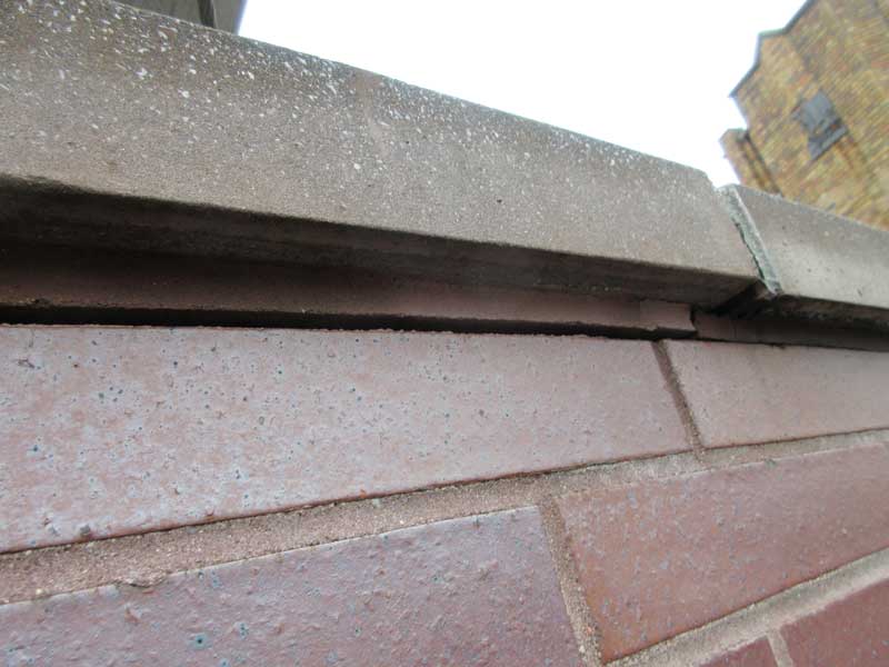 [4]
[4]A continuous brick veneer column located between windows was 18 m (60 ft) or six floors tall, with moisture expansion of 9 mm (0.36 in.). This is calculated with:
(0.06 x 6)
= 0.36 in.
This occurred in addition to thermal expansion at the south elevation of 9.3 mm (0.37 in.), calculated with:
(0.0624 x 6)
= 0.37 in.
Total brick veneer expansion was 19 mm (3/4 in.), accumulating at the top of the building and shifting up the sixth-floor loose lintel for 19 mm. It was calculated with:
(0.36 + 0.37)
= ¾ in.
The CMU backup wall shrinkage would be 16 mm (5/8 in.), calculated with:
(0.1 x 6)
= 0.6 in.
This means the top floor windows attached to the CMU backup wall will shift down for 16 mm.
Total differential movement between the expanding brick veneer and shrinking CMU backup wall would be 35 mm (1 3/8 in.) at the sixth floor, calculated with the following:
(3/4 + 5/8)
= 1 3/8 in.
Brick veneer was anchored to the CMU backup wall with adjustable hook and eye masonry ties, and at the sixth floor, the hooks could be off the eyes due to this differential movement. Therefore, continuous shelf angles should be provided to support the brick veneer at every floor level.
Conclusion
When differential movement between expanding brick veneer and shrinking CMU accumulates at the top of the building, it can cause shifting of the parapet coping stones, and unsafe conditions. With introduction of the continuous shelf angles bolted to the CMU bond beams at every floor level, and a horizontal expansion joint under each shelf angle, this accumulation—and all its associated problems—can be eliminated.
Michael Gurevich is a masonry consultant at the New York City Brickwork Design Center (NYCBDC), which conducts seminars on a variety of brick masonry topics. He has more than three decades of experience working with exterior masonry walls. Gurevich holds a master’s degree in structural engineering from Belarussian State Polytech University in Minsk. He can be contacted via e-mail at nycbdc@aol.com[5].
- [Image]: https://www.constructionspecifier.com/wp-content/uploads/2017/09/bigstock-Architecture-concept-brick-bu-15985592.jpg
- [Image]: https://www.constructionspecifier.com/wp-content/uploads/2017/09/IMG_0609.jpg
- [Image]: https://www.constructionspecifier.com/wp-content/uploads/2017/09/IMG_0614.jpg
- [Image]: https://www.constructionspecifier.com/wp-content/uploads/2017/09/IMG_0956.jpg
- nycbdc@aol.com: mailto:nycbdc@aol.com
Source URL: https://www.constructionspecifier.com/designing-brick-veneer-loadbearing-exterior-walls/