

The paper introduces a simpler, but accurate, way to calculate the effect of thermal bridging. Rather than calculate the cross-sectional areas of building elements and work out heat loss per area, the modeler only has to measure the length of the thermal bridge (e.g. the length of the deck or perimeter of a window), or identify point sources (e.g. a penetrating structural beam). Each element has a thermal transmittance value already determined by the research. Linear transmittance is measured in W/(m•K) and point flow is measured in W/K.
The opaque wall, without any thermal bridging, is the ‘clear wall’ for which the thermal transmittance value has been predetermined and validated. It is measured in W/(m2•K). For an insulated stud wall, all components—including the air films, studs, batts sheathing, insulation, cladding, and fasteners—are included.
To calculate the thermal bridging effect of a cantilevered balcony, for example, the length of the balcony at the wall interface is multiplied by the linear transmittance value. This number is then divided by the area of the wall, before then adding the increased thermal transmittance to the ‘clear wall’ value. If a whole elevation is calculated, then the lengths of all balconies, windows, doors, shelf angles, and other linear penetrations are added. Point penetrations are also calculated and added. Once all the values are added to the ‘clear wall’ value, the result should be the total effective assembly thermal transmittance.
The complete method is described in Morrison Hershfield’s Building Envelope Thermal Bridging Guide, Version 1.1. (Building Envelope Thermal Bridging Guide, Version 1.1, was prepared by Morrison Hershfield and published by BC Hydro Power Smart in 2016.) The guide is based on research done for ASHRAE, plus additional research funded by a number of industry partners such as the EIFS Council of Canada. (This comes from Table 1 of the 2014 “Thermal and Whole Building Energy Performance of Exterior Insulated Finishing Systems Assemblies,” Report No. 5130962.00, by Morrison Hershfield Ltd. Visit www.eifscouncil.org.) The method, compared to previous data manipulations, is elegantly simple. The result, compared with what is allowed in a local building code, may be surprising.
In fact, the real fun of determining the effective thermal transmittance of a proposed building begins when one realizes it does not comply with the code. That dilemma will increase as different code bodies start stretching the codes to meet the demands for more thermally efficient buildings. It is at that point where designing and building to eliminate thermal bridging will get serious.
Comparing methods of construction
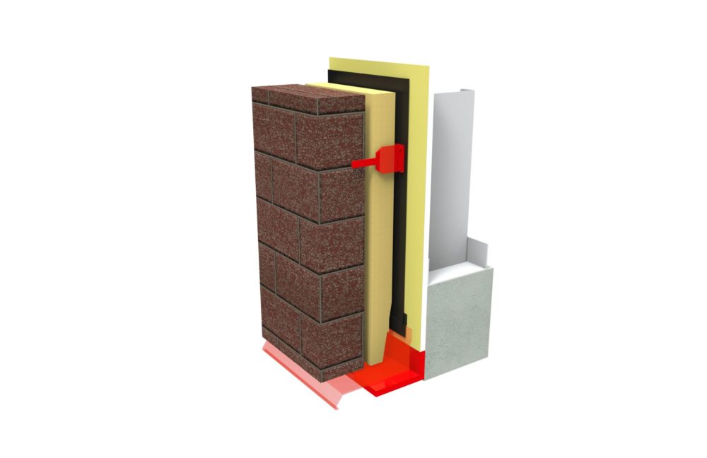
Comparing brick and EIFS details illustrate how different elements can affect the thermal transmittance of a wall. Constructions similar to the brick veneer wall assembly supported by a steel shelf angle are common (Figure 4). Exterior insulation is used, often 50 mm (2 in.) for a nominal R-8 to R-10 value. The thickness and subsequent R-value are limited by the size and projection of the shelf angle.
The insulation is not continuous, of course, because of the projecting shelf angle. If the steel stud cavity has batt insulation, then a nominal R-12 for a 92-mm (3 5/8-in.) stud space is added. Considering the insulation alone, this could be a nominal R-22 wall.
Until recently, the thickness of the steel shelf angle has been considered a minor thermal bridge through the insulation, because the cross-sectional thickness of the steel shelf is relatively small compared to the area of the wall. However, the Morrison Hershfield research has shown this thermal bridging effect can reduce the effective R-value of the ‘clear wall’ by more than 30 percent. Since many variables affect this calculation, practitioners who want to work out the linear transmittance for their design should refer to the Building Envelope Thermal Bridging Guide.
The effective thermal performance of this design can be improved with more energy-efficient details. For example, moving the shelf angle out from the wall using clip assemblies (e.g. knife plates, hollow structural steel [HSS] sections, or overlapping angles) reduces the area of thermal bridging. Continuous insulation can be installed between the shelf angle and the wall. Optimized clip design, spacing, and materials can improve thermal performance to 15 percent clear wall reduction range. Using proprietary insulated connections can make further improvements with reductions of only seven percent from the ‘clear wall’ value. (“Masonry Veneer Support Details: Thermal Bridging,” was presented by RDH Building Engineering Ltd.’s Michael Wilson, M.Eng, Graham Finch, MASc, P.Eng., and James Higgins Dipl.T, at the 12th Canadian Masonry Symposium, held in Vancouver in June 2013.)
An additional consideration for brick veneer is the choice of brick ties. In terms of cross-sectional area of the brick tie as a ratio to the gross wall area, the brick tie might appear insignificant in terms of its thermal bridging. A paper published in 2013 suggests this assumption would be a mistake. Based on tie material and design, the effective R-value reduction of the exterior insulation can be from “… five to almost 30 percent…” (“Thermal Bridging of Masonry Veneer Claddings & Energy Code Compliance” was presented by the same authors at the same conference as in Note 4.)
The brick wall in Figure 4—from sheathing to the face of the brick, including 50 mm of continuous insulation—could have a dimension of approximately 180 mm (7 in.) with an approximate effective R-18 value (versus a nominal R-22) if all the design improvements are made to the details. Again—designers should make their own calculations based on the BETB Guide.

