Designing sound isolation in multi-family living
by Katie Daniel | January 9, 2015 11:56 am
 [1]
[1]by Alicia Larsen, Benjamin Markham, LEED AP, and Jeffrey A. Zapfe, PhD
Imagine moving into a new condo, only to realize the TV next door, the dog barking across the hall, and the neighbors walking around upstairs can all be easily heard. Acoustical consultants would love to help, but unfortunately there is little that can be done at this stage without significant cost and intrusion. Sound isolation issues are most effectively addressed before construction, during the design phase.
What can designers of multi-family buildings do to meet the sound isolation expectations of their client and future residents? Acoustical consultants use several techniques to address these issues. However, before delving into them, one must first understand a little bit about sound.
Every sound isolation problem has three elements—a source, a path, and a receiver. The ‘source’ is the noise generator. It could be anything from a fourth-grader practicing her saxophone to a piece of building mechanical equipment. In many cases, the most effective means of mitigating a noise concern is to choose a quieter source if possible (e.g. quieter mechanical equipment), or to increase the distance between the source and sensitive receivers (i.e. lengthen the path).
Unfortunately, many times the source is an element that cannot readily be changed. No matter how many rules you put in place, there is no guarantee the student will stop practicing her saxophone at odd hours or the man next door will not fall asleep with his TV on again.
The ‘path’ is the element designers have the most control over, and so it is what frequently receives the most focus during the design. Both the path’s length and the building constructions intervening between source and receiver (position and composition) can be controlled. The performance of those building components is predictable and does not rely on residents’ behavior to be successful.
Finally, the ‘receivers’ in a multi-family building are the residents. Individual sensitivity to noise or vibration varies, so designers have little control over this piece of the sound isolation puzzle. One exception is the background noise level in a residence—designers can control this aspect by introducing steady, broadband (full-spectrum) ambient sound that masks the intruding sound, similar to the ‘white-noise’ machines some people use in their bedrooms to help them sleep. The bottom line is ‘quiet’ does not equate to ‘private’—in fact, it is just the opposite: there is greater privacy when there is a steady (but pleasant) level of ambient sound present.
Given the design team has the greatest control over the path, this article focuses on this design aspect—namely, how to design building components that provide substantial sound isolation. To add just a little more complexity, there are really two types of sound transmission to be considered in multi-family buildings: airborne and impact.
Airborne sound transmission
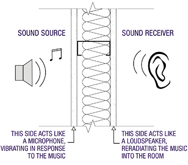
Airborne sound is generated, and primarily travels to the receiver, in the air. This is most of the sound heard on a daily basis, with examples including people talking or a loud stereo system. In a room-to-room situation, airborne sound can transmit either through a gap in the construction (e.g. a door undercut) or directly through a wall by causing the intervening construction to vibrate and re-radiate the sound energy on the other side.
Figure 1
 [2]
[2]For example, with a single-stud partition, one side (the source side) can be thought of as a microphone, and the other side (the receiver side) as a loudspeaker (Figure 1). The sound energy travels through the air and gets picked up by the ‘microphone,’ transmits through the structure, and is re-radiated by the ‘loudspeaker’ into the air on the other side of the partition.
In this case, there are three primary methods to improve sound isolation:
- ?Seal all gaps, cracks, and leaks. This is the easiest and most effective means to isolate sound. Sound will always find the weakest path—other attempts to improve sound isolation will be ineffectual if the gaps are not sealed first.
- ?Increase the mass of the construction. This makes it more difficult for the airborne sound to cause the partition to vibrate. In the microphone/loudspeaker analogy, this corresponds to making the microphone and loudspeaker less effective or efficient.
- ?Introduce decoupling into the construction. This allows one side to vibrate without transferring the vibration as easily to the other side. This is analogous to cutting the physical connection between the microphone and loudspeaker.
In many cases, all three methods are necessary.
Closing gaps
ASTM C919, Standard Practice for Use of Sealants in Acoustical Applications, contains recommendations on how to apply caulk in acoustical applications. Ideally, all penetrations should be sealed. Back-to-back electrical boxes should be staggered, preferably in different stud bays, and caulked. Walls should be caulked with one bead on each side of the partition. (A second bead of caulk on one or both sides of the partition does not result in a substantial improvement in sound isolation.)
Windows and entry doors should be effectively gasketed. Poorly sealed entry doors (particularly those that have a substantial undercut) can be a significant source of noise intrusion from corridors into residences.
 [3]
[3]Increasing mass
A substantial increase in mass is necessary to have a meaningful effect on a partition’s sound isolation performance. (‘Substantial’ normally means in terms of a factor of two times heavier.) This could be accomplished by upgrading from one to two layers of gypsum board on each side of a stud partition, or using plaster rather than gypsum board. (Plaster has roughly three times the mass of gypsum board.) If partitions are concrete masonry unit (CMU), increasing the density or thickness, or filling the CMU cavity with grout, can effectively increase the mass.
Introducing decoupling
The goal is to eliminate rigid connections between one side of the construction and the other. The most effective way to do this is by using a double-stud or double-width construction with an air cavity between the two sides of the wall. When double walls are not possible due to cost or space constraints, other methods such as specialty resilient fasteners can be acceptable alternatives. In general, resilient clip products tend to be more reliable than resilient channels, but either product can be compromised in real-world applications, particularly if cabinets, TVs, or other wall-mounted elements must be anchored directly to the studs. Such complications are less prevalent in suspended ceiling applications in place to increase up-down sound isolation.
Impact sound transmission
Impact sound is produced by forces applied directly to the structure or partition. The most common example of this is people walking on the floor above, but things like chairs scraping along the floor and the thump of people ascending/descending stairs are also prevalent in multi-family buildings.
The sound isolation methods that are discussed for partitions can also ?be used in order to mitigate impact sound. A few others are discussed in the following paragraphs.
Increase the structure’s stiffness
Floor stiffness is an important first step in mitigating impact sound (particularly the low frequency ‘thuds’). Unfortunately, increasing the structure’s stiffness can be challenging when the construction is already determined. As a rule, the stiffer the structure, the more effective the sound and vibration isolation will be, particularly at low frequencies. Structures that are not stiff do not generally isolate the low-frequency content of impact sounds, no matter what other mitigation means are employed.
Decoupling
Decoupling works like a shock-absorber on a car. Energy is applied to one side of the construction, but the way in which the sides of the construction are connected prevents the energy from being efficiently transmitted to the other side (the sides of the construction are often connected by a device such as a spring or a resilient pad). A car can go over a bump, but since the wheels attached to the shock absorber move up and down relatively freely, the passengers do not feel the bump to the same degree in their seats.
 [4]
[4]Carpeting and other ‘soft’ floor finishes significantly cushion impact sounds, preventing the floor/ceiling assembly from becoming energized in the first place. Most impact sound problems occur with hard floor finishes like wood or tile. In most cases, addressing this issue with decoupling is the most sensible option, as it often has the fewest implications on the project.
The structure’s stiffness is typically decided in the earliest stages and changing it could have major cost implications. On the other hand, the finish floor hardness is often decided based on aesthetic considerations; changing the finished floor may or may not be an option.
Decoupling can be addressed on the floor side or on the ceiling side. On the floor side, a resiliently supported massive layer (a floating floor) is used to provide isolation. Floated floors can range from a separately poured concrete slab that rests on resilient isolators to a thin underlayment underneath the finished floor. The required scale of the decoupling depends on the amount of isolation needed.
One can also introduce decoupling on the ceiling side by installing a resiliently suspended ceiling. Again, depending on the application, this can range from hanging multiple layers of gypsum board on a network of spring hangers to attaching the gypsum board using resilient channels. (In best cases, decoupling is introduced both at the floor and at the ceiling.)
In either case, it is best to begin with a stiff structure. When faced with an existing structure that lacks stiffness, it is typically necessary to add structural members (e.g. more beams) or increase mass (e.g. pour more concrete).
Wood-frame construction is fairly limp to begin with, so addressing the stiffness can make a large difference on the effectiveness of the sound isolation. At least 25 mm (1 in.) of gypsum concrete in wood-frame constructions goes a long way to stiffen the structure and add mass. Steel and concrete buildings tend to be stiffer, but sometimes even they require additional steel framing or concrete to provide adequate impact isolation.
Quantifying sound isolation
Various metrics put forward in the following ASTM standards are used to quantify the sound transmission between spaces and assign a single-number rating to the airborne sound transmission or the impact sound transmission:
- ?field: ASTM E336, Standard Test Method for Measurement of Airborne Sound Attenuation Between Rooms in Buildings;
- ?laboratory: ASTM E90, Standard Test Method for Laboratory Measurement of Airborne Sound Transmission Loss of Building Partitions and Elements;
- ?field: ASTM E1007, Standard Test Method for Field Measurement of Tapping Machine Impact Sound Transmission Through Floor-Ceiling Assemblies and Associated Support Structures; and Measurement of Impact Sound Transmission Through Floor-Ceiling Assemblies Using the Tapping Machine.
Airborne sound transmission is typically quantified using the sound transmission class (STC), which is a laboratory rating that cannot be measured in the field. Field equivalents include apparent STC (ASTC) and noise insulation class (NIC). The major difference between the two field ratings is ASTC is normalized to account for the room acoustics in the particular measurement scenario.
Using ASTC, the performance of two different constructions, in two different locations, with different source and receiver room types, can be compared. ASTC is a test that would be used to measure compliance to a design standard. NIC, on the other hand, does not normalize for the room conditions—as such, it better represents what the occupants actually experience rather than simply how the partition is performing.
In all cases (i.e. STC, ASTC, and NIC), higher values indicate better sound isolation.
Impact sound transmission has an analogous set of metrics:
- ?impact insulation class (IIC), the lab rating;
- ?apparent IIC (AIIC), the normalized field measurement used to determine compliance; and
- ?impact sound reduction (ISR), the non-normalized field measurement that correlates well to occupant experience.
Again, higher values indicate better sound isolation.
Physically, a partition’s sound isolation depends on the frequency of the sound. In most cases, partitions tend to isolate higher frequency sound better than low frequencies. Unfortunately, the single-number metrics all combine this frequency-dependent behavior into a single numerical rating. This means the ratings alone may not fully describe the performance.
For example, the two tests shown in Figures 2a and 2b have the same IIC rating, but very different properties of impact sound isolation across frequency. The first fits the AIIC 54 curve closely, whereas the second shows deficiencies at low frequencies and good performance at mid- and high-frequencies. With the floor-ceiling construction associated with 2b, one would be able to hear a 13.5-kg (30-lb) toddler jumping up and down, but not the click of his mother’s high heels.
Figure 2
 [5]
[5]A change in STC or IIC of one or two points is not an appreciable difference in sound isolation. However, a change of five points is significant, and a change of 10 points typically corresponds to a largely significant difference—on the order of a doubling or halving of the perceived loudness of the intruding sound.
Code requirements/guidelines
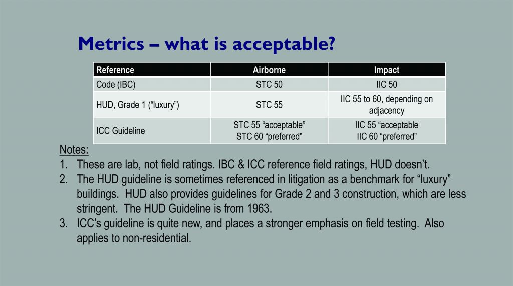
Many states have adopted the International Building Code (IBC) into their state building code requirements. This calls for a minimum STC 50 laboratory rating, or 45 if measured in the field. Similarly, impact sound isolation requirements are IIC 50 or 45 if measured in the field.
It is important to understand these code requirements do not necessarily equate to occupant satisfaction, and certainly do not indicate inaudibility. Higher values are recommended for more sensitive applications. Figure 3 shows a summary of various sound isolation guidelines commonly referenced in the industry.
Figure 3
 [6]
[6]Ground-borne vibration and sound ?from rail lines
Multi-family residential structures are typically found in densely populated urban areas. Many of these urban areas also have extensive public transportation systems, some of which incorporate underground rail lines. Anyone who has visited New York City, Chicago, or Boston has likely encountered the characteristic low frequency rumble from a passing subway train.
Interestingly, vibration is actually the mechanism responsible for the rumble sound. Micro-forces due to imperfections at the wheel-rail interface produce vibration that travels through the soil to nearby buildings. Once inside the building, the vibrations cause the walls, floors, and ceiling to vibrate and radiate sound much like giant loudspeakers. It is this radiated sound people hear when the train passes. With the exception of air vents and other openings, the acoustic sound produced by the train in the tunnel is effectively trapped inside the tunnel.
If the vibration is sufficiently severe, people may feel it, but more often than not, the vibrations cannot be felt even though the resulting sound can still be heard. Since the vibration is propagated through the soil, the resulting sound and vibration inside the building are commonly referred to as ground-borne. Surface rail systems also produce ground-borne sound and vibration, although this is often masked by the direct airborne sound from the passing train.
The Federal Transit Administration (FTA) provides guidelines for acceptable levels of ground-borne vibration and sound in residential settings where people normally sleep. While these levels strictly apply to new transit projects near existing communities, they also can be used as a reasonable guideline for a new residential structure near an existing rail line. Unfortunately, FTA does not specifically say what the effects will be if its limits are exceeded.
More insight into this aspect is available from the TCRP D-12 study. The D-12 project studied the relationship between ground-borne vibration and sound and community annoyance and provided a method to estimate the likelihood of annoyance based on the vibration or sound exposure level.
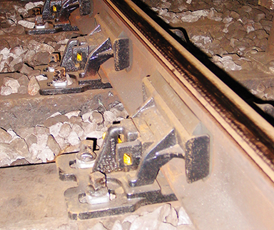
Like airborne sound, mitigation of ground-borne sound and vibration can be conceptualized in terms of the source, path, and receiver. In addition to effective maintenance of the track and rolling stock, source mitigation treatments usually involve a resilient track support. Such supports come in many varied forms, but the basic concept involves the placement of a resilient element (rubber, neoprene or even steel spring) between the rail and the tunnel floor. Figure 4 is one example of a resilient track fastener that is located between the rail and the wood tie. Resilient track supports can be very effective at reducing vibration, however, they also require the direct involvement of the transit agency, whose cooperation can be challenging to secure.
Figure 4
 [7]
[7]Path mitigation has limited effectiveness for ground-borne vibration. Trenches are often proposed as a mitigation option, but in addition to being of limited practicality in an urban setting, their effectiveness is modest at best.
Mitigation at the receiver is a viable option, particularly for new construction. Buildings have a natural vibration attenuation of one or two decibels per floor as one moves up away from the source. There is also distance attenuation as one moves farther from the rail line. Designers can take advantage of this by locating the most sensitive receivers on upper floors, saving the lowest levels for less-sensitive uses such as parking, mechanical, and retail.
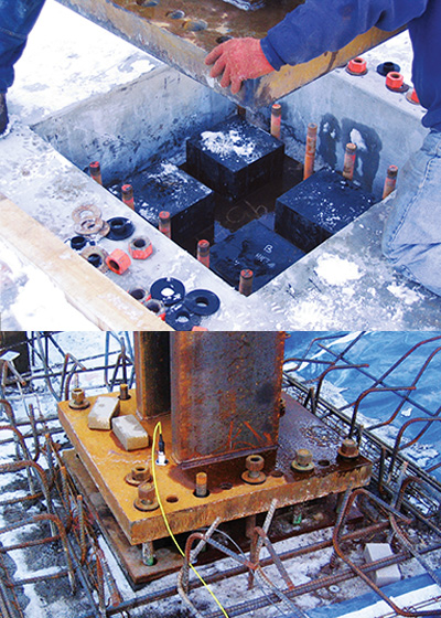
More active steps can also be taken to reduce the amount of vibration entering the building at the foundation. Base isolation systems are used to support the building resiliently. Base isolation is typically done at the column base (Figure 5), although continuous pads under mat foundations can also be employed. The isolation performance of the isolation is specified based on the source levels (train) and the design goals for the living spaces. Vibration reductions associated with a base isolation system are comparable to what would be expected from a track isolation system.
Figure 5
 [8]
[8]Mitigation is also possible within the building on a room-by-room basis. ‘Room-within-a-room’ construction using a floated floor and resiliently supported walls and ceiling can be effective provided constructability challenges such as differential floor heights can be addressed.
Conclusion
Sound and vibration isolation comes down to mass, stiffness, and de-coupling. In multi-family buildings, it is necessary to consider wall constructions, floor/ceiling assemblies, and environmental noise and vibration sources with these factors in mind. It is sometimes said good fences make good neighbors. In a multi-family building, good building constructions can make for good neighbors, too.
| Sound Isolation Pitfalls |
 [9] [9]1. Some ‘resilient channels’ are not really resilient. Two-legged resilient channels do not provide a meaningful acoustical benefit. |
Alicia Larsen is a consultant in acoustics at Acentech, a multi-disciplinary acoustics, audiovisual systems design, and vibration consulting firm. Her special interests include sound and vibration isolation for mixed-use buildings, community noise issues, and acoustical measurement and analysis. Larsen has presented her graduate and consulting work at the Acoustical Society of America (ASA) and Institute of Noise Control Engineering (INCE) national conferences, and chaired ASA’s Greater Boston Chapter. She can be reached at alarsen@acentech.com.
Benjamin Markham, LEED AP, is the director of architectural acoustics at Acentech, and an acoustician involved in projects concerned with performance spaces and other commercial, residential, and civic facilities. He also teaches classes in architectural acoustics at Massachusetts Institute of Technology (MIT) and Cornell University. Markham can be contacted via e-mail at bmarkham@acentech.com.
Jeffrey A. Zapfe, PhD, is Acentech’s president. His expertise is in the area of vibration, structural dynamics, vibration sensitive facilities and equipment, and vibration isolation. Zapfe’s work includes the analysis of structures at the design stage as well as the measurement, analysis, and mitigation of vibration in completed buildings. He can be reached at jzapfe@acentech.com.
- [Image]: http://www.constructionspecifier.com/wp-content/uploads/2015/01/Acoustic_Rendering-Twenty-20-Credit-CBT-Architects.png
- [Image]: http://www.constructionspecifier.com/wp-content/uploads/2015/01/Acoustic_Acentech_Figure-1.png
- [Image]: http://www.constructionspecifier.com/wp-content/uploads/2015/01/Acoustic_Concord-Park-Residential-Multi-Unit.png
- [Image]: http://www.constructionspecifier.com/wp-content/uploads/2015/01/Acoustic_Berklee-Tower-c-Robert-Benson-Photography.png
- [Image]: http://www.constructionspecifier.com/wp-content/uploads/2015/01/Acoustic_Acentech_Figure-2-2.jpg
- [Image]: http://www.constructionspecifier.com/wp-content/uploads/2015/01/Acoustic_Acentech_Table-1-2.jpg
- [Image]: http://www.constructionspecifier.com/wp-content/uploads/2015/01/Acoustic_Acentech_GBV_Fig4.png
- [Image]: http://www.constructionspecifier.com/wp-content/uploads/2015/01/edited.jpg
- [Image]: http://www.constructionspecifier.com/wp-content/uploads/2015/01/Acoustic_Acentech_Figure-3.png
Source URL: https://www.constructionspecifier.com/designing-sound-isolation-in-multi-family-living/