Designing the overlooked transition between air barrier and fenestration
by arslan_ahmed | December 1, 2023 4:00 pm
 [1]
[1]By Kevin Haynes
Designing the transition between an effective air barrier and fenestration, such as curtain wall and storefront, can present challenges for the designer and specifier. During the design phase, the process of selecting and specifying a curtain wall and/or storefront, in some cases is limited to aesthetics, structural considerations, thermal performance, and cost. Too often, the interface between the air and water barrier and fenestration are overlooked. The goal is to maintain continuity of the air and water barrier (AWB) assembly and its connections with the building components to ensure the building’s performance and long-term durability.
Specifying an air barrier system in commercial buildings can improve indoor air quality (IAQ), provide energy savings by reducing heating and cooling cost, help control air leakage, and support sustainable design. Uncontrolled air leakage and moisture within the building envelope can affect building occupants and may cause premature deterioration of materials, leading to costly damages. An effective AWB controls both air leakage and vapor diffusion through the building envelope, helping prevent materials’ deterioration. A greater amount of moisture is due to air leakage moving through a wall or roof compared to the amount of moisture attributed to vapor diffusion.
Air barrier assemblies
Air barriers consist of various materials and assemblies, and all are intended to manage air flow between unconditioned and conditioned space. It is also important that the air barrier assembly controls air leakage, bulk water intrusion, vapor diffusion, and thermal performance. The selection and specification process should consider the building type, the project location (climate zone), and the performance requirements.
There are at least six types of manufactured air barrier systems available:
- Self-adhered membranes
- Liquid-applied membranes
- Mechanically attached – building wraps
- Insulating board stock – rigid insulation
- Spray polyurethane foam (SPF)
- Factory-bonded – membranes to sheathing
Determining what types of manufactured air barrier systems work best with curtainwall/storefront system, it really comes down to the design of the interface between the wall and the glazing system. The key is that the continuity of building envelope barrier is maintained and compatibility between materials is assured.
Compatibility between the air barrier materials and the glazing assemblies, such as curtain wall and storefront, is critical to maintain a weather-tight barrier. Depending on which air barrier is specified, chemical and adhesion compatibility needs to be addressed in the design phase to ensure proper interface between materials.
Storefront, curtain wall, sealants, backer rods, and transition membranes are components of the air barrier assembly. It is important for the designer and specifier to understand the difference between curtain wall and storefront systems, especially regarding air and water tightness. This will help determine the interface with the AWB and the critical seal location (wet/dry line)
of the curtain wall verses storefront systems.
 [2]
[2]Thermal performance must also be considered to maintain optimal energy efficiency in the building. Overall thermal performance in the wall assembly can best be achieved by aligning the wall insulation with the thermal break/isolator in the storefront and curtain wall system. Avoid thermal “short circuits” where conductivity occurs in flashing, masonry sills, and lintels that extend into the interior.
When the building envelope’s thermal break is compromised, heat loss and heat gain can result. In addition to consuming resources and increasing operational costs, a building’s poor thermal performance can affect interior temperature management and may promote condensation. When moisture is present, it can lead to mold, mildew, and other potentially harmful microorganisms. Unhealthy, unsightly, and uncomfortable interiors can have a negative impact on people’s wellness and absenteeism, concentration, productivity, and job satisfaction. Building owners also can experience a negative impact in lower lease rates, more vacancies, and reduced property value.
Code compliance
Model building energy codes and standards, including the International Building Code (IBC), and the International Energy Conservation Code (IECC), and ASHRAE Standard 90.1, Energy Standard for Sites and Buildings Except Low-Rise Residential Buildings, require controlling air leakage through the design and construction of a continuous air barrier in the building envelope.
The 2018 IECC notes a continuous air barrier is required in all U.S. climate zones except Zone 2B. Zone 2B comprises a handful of locations with warm, dry climates, such as Arizona’s Yuma County, California’s Imperial County, and Texas’ Real County.
IECC section 402.5.1 says air barriers may be located inside the building envelope, outside the building envelope, within the assemblies’ composing envelope, or any combination thereof. Air barrier compliance methods follow in sections:
- C402.5.1.2.1 Materials, which states, “Materials with an air permeability not greater than 0.004 cfm/ft² (0.02 L/s•m2) under a pressure differential of 0.3 inch of water gauge (75 Pa) when tested in accordance with ASTM E2178 (Standard Test Method for Determining Air Leakage Rate and Calculation of Air Permeance of Building Materials) shall company with this section. Materials… shall be deemed to comply with this section, provided that joints are sealed and materials are installed as air barriers in accordance with the manufacturer’s instructions.”
- C402.5.1.2.2 Assemblies, which states, “Assemblies of materials and components with average air leakage not greater than 0.004 cfm/ft² (0.02 L/s•m2) under a pressure differential of 0.3 inch of water gauge (75 Pa) when tested in accordance with ASTM E2357 (Standard Test Method for Determining Air Leakage Rate of Air Barrier Assemblies), ASTM E1677 (Standard Specification for Air Barrier (AB) Material or Assemblies for Low-Rise Frame Buildings Walls) or ASTM E283 (Standard Test Method for Determining Rate of Air Leakage Through Exterior Windows, Skylights, Curtain Walls, and Doors Under Specified Pressure Difference Across the Specimen) shall company with this section. Assemblies… shall be deemed to comply with this section, provided that joints are sealed are the requirements of Section C402.5.1.1 are met.”
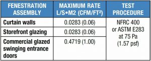
The air leakage of fenestration assemblies is determined in accordance with AAMA/WDMA/CSA 101/I.S.2/A440, North American Fenestration Standard/Specification for windows, doors, and skylights (NAFS), ANSI/NFRC 400, Procedure for Determining Fenestration Product Air Leakage, or ASTM E283. Along with storefront and curtain wall, fenestration in architecture refers to openings in the building envelope that include windows, doors, skylights, vents, and more.
A sampling of maximum air leakage rates for fenestration assemblies per the 2018 IECC C402.5.2 Table include:
Key considerations: Curtain wall
Storefront and curtain wall systems share similar functions and appearance. Both can protect the building and its occupants from weather, while providing daylight to the interior and views to the outside. Beyond these commonalities, these fenestration systems have numerous differences in how each best suits its intended application.


Curtain wall is a non-load-bearing exterior wall cladding that is hung to the exterior of the building, usually spanning multiple floors. It also can be used in large spans and punched openings on mid-rise to high-rise buildings. Glazing in-fills, such as glass, can be installed as captured or structural silicone glazed (SSG) method. Captured uses a pressure plate or pressure bar that is fastened to the back member mullion. Gaskets form the seal to limit air and water intrusion. Face caps provide an aesthetic appearance and conceal the pressure plate fasteners. The SSG method eliminates pressure plates and gaskets, and relies on sealant to create an adhesive bond on the interior side of the glass and back member. This can occur at the verticals or horizontals, or both to create all-glass appearance.
There are two main classifications of glazed curtain wall: stick-built and unitized. In stick-built curtain wall systems, the frames, glass, and/or in-fill panels are furnished as individual components and installed on site, piece by piece or in pre-assembled sections. Unitized curtain wall are modular systems composed of large units, usually spanning floor-to-floor that are assembled and glazed in the factory, shipped to the job site, and erected in sequence on the building.
Curtain wall systems perform at a high level, especially when considering air and water management. Rather than attempting to drain the entire frame, curtain wall systems isolate water within each individual lite of glass. This occurs in the glass pocket that captures the insulated glass units (IGUs).
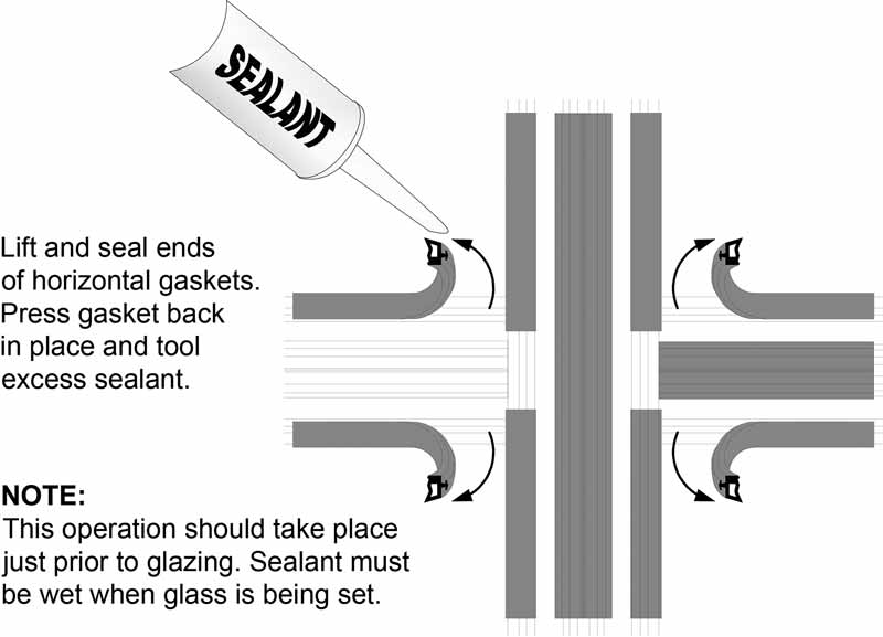
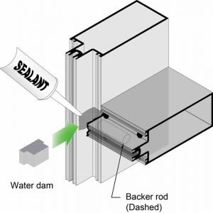
Weep holes installed in the pressure plate and face caps allow water to drain to the exterior, as well as create pressure equalization. After assembling the vertical and horizontal back member mullions together, water dams are installed using sealant (Figure 1).
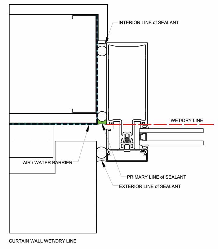
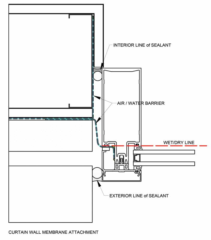
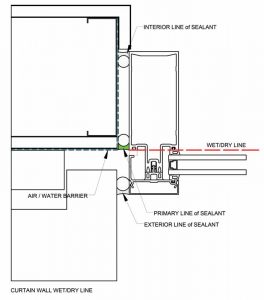
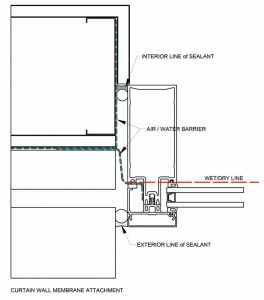
Prior to setting the IGUs, interior gaskets are sealed in each corner (Figure 2), creating the critical seal on the interior side of glass pocket and insulated glass. This is the location of the wet/dry line as illustrated in (Figure 3).
Of equal importance is recognizing the location of the primary line of the perimeter sealant, which is crucial in maintaining the continuity of the AWB. In stick-built curtain wall, the primary line of sealant is installed behind the glass in the same plain as the wet/dry line. In this case, the perimeter sealant and backer rod provide the transition from the curtain wall wet/dry line and the air water barrier (Figure 3). The transition between the curtain wall and the opaque wall must allow for both thermal and differential movement. The sealant joint installed at exterior face of the curtain wall is a weather seal and is not the primary line of sealant.
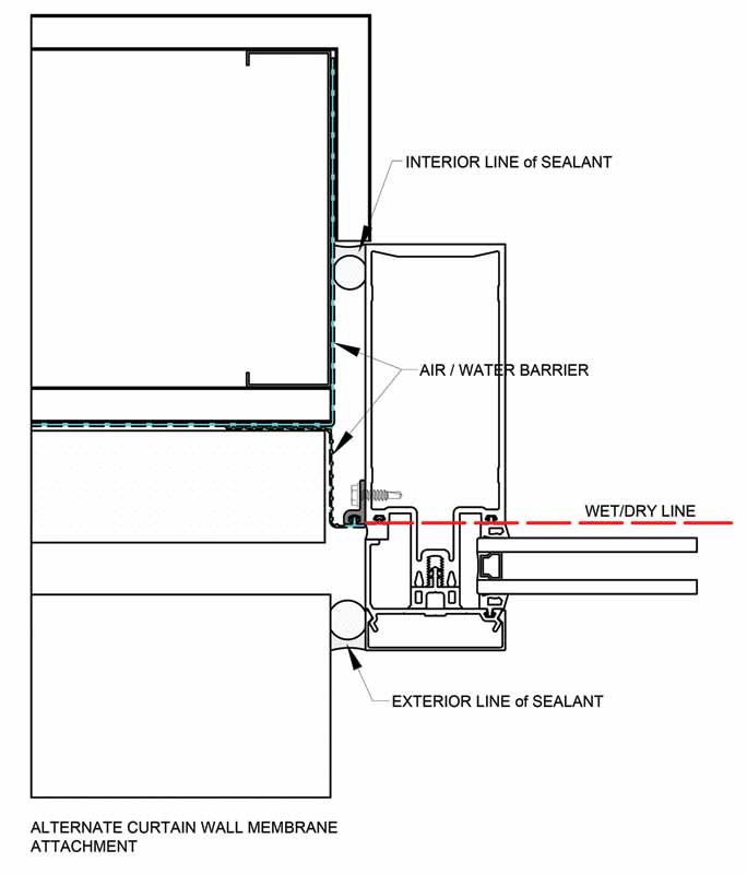
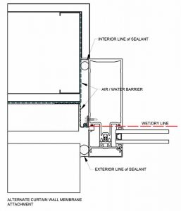
When it is not possible to install the primary perimeter sealant joint, a transition membrane is often detailed. This is normally achieved by using pre-formed silicone sheets that attach to the glass pocket of the curtain wall prior to installing the pressure plate and face cap (Figure 4). Curtain wall manufacturers have developed specialized extruded adapters that connect the silicone sheet membrane directly to the curtain wall at the perimeter of the frame (Figure 5). Designers and specifiers have numerous other options in detailing the transition between the AWB and the curtain wall assemblies. To ensure the best possible solution, consulting the curtain wall manufacturer in the design phase is recommended.
Since curtain wall assemblies are considered non-load bearing walls, they must be supported by the building structure. In stick-built systems, curtain wall typically relies on “T” and “F” anchors installed in the top and bottom of the vertical mullions and jamb members. The anchors are designed to withstand the imposed structural loads and to accommodate movement between the building structure and curtain wall assemblies.
Additional anchor methods include perimeter “F” clips and, for curtain wall assemblies spanning multiple floors, steel angles are used to connect vertical mullions at each floor slab. The transition of the AWB to the curtain wall must be completely sealed at the anchors, and accommodate shims, adjustments, and building movement. It is crucial that transition membranes are installed in a manner that does not interfere with or block installed weep holes, preventing proper drainage of the curtain wall.
Installation must work in sequence involving coordination between trades to ensure a continuous, completely sealed AWB is achieved in the building envelope. However, the sequence may vary depending on the type of AWB specified and the fenestration selected. For practical purposes, the interface between the installed curtain wall and the AWB assembly should be completely sealed prior to installing the surrounding cladding. In this manner, all seals and connections within the AWB, transition assembly, and curtain wall can be inspected and tested to address any issues, if necessary.
Key considerations: Storefront systems
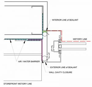
Storefront systems are the most economical commercial glazing assembly available due their simplicity. However, they are limited in size, performance, and where they should be used on a building. Today’s storefront systems are typically stick-built and pre-assembled in small sections, making it easier to transport to the job site, and they can be installed in sequence within the building openings. In this process, sealant is applied between the connection in the horizontal and vertical members prior to assembling the frame sections. The critical seal is located on the interior side of the glass pocket behind the glass.
In storefront, the entire elevation is drained at the bottom of the frames with internal drainage occurring in the glass pocket area, whereby water is directed from the horizontal, down the vertical mullions using water deflectors. Sub-sill flashing installed underneath the frame is an integral part of the drainage process. The flashing includes a vertical leg at the interior side and end dams installed on each side forming a panning condition. Bulk water is contained in the sub-sill flashing and drained to the exterior through weep holes.
 [3]
[3]Since storefront consist of open back frame members at the perimeter and sub-sill flashing, the actual air and water seal is located at the interior side of the frame. Therefore, the wet/dry line is not a continuous plane; it is offset to the interior side of the storefront frame (Figure 6). This is important when designing the interface or transition from the storefront to the AWB.
To conclude, designers and specifiers should consider the following design criteria when considering the building envelope AWB and fenestration:
- Transition of the AWB assemblies and fenestration needs to align as close as possible.
- Connections must accommodate anchors, shims, adjustments, and building movement maintaining continuity of the building envelope AWB.
- Avoid thermal “short circuits” and align thermal breaks
in fenestration with surrounding wall insulation to optimize energy performance. - Coordination between trades is recommended, allowing for installation to work in sequence. Curtain wall and storefront frames need to be installed and sealed prior to the cladding being installed.
 Author
- [Image]: https://www.constructionspecifier.com/wp-content/uploads/2023/11/OR_Slate_9039JoshuaJayElliott-courtesyWorksProgressArchitectureLLP.jpg
- [Image]: https://www.constructionspecifier.com/wp-content/uploads/2023/11/Tubelite_MN_DC-Group_PaulCrosby077.jpg
- [Image]: https://www.constructionspecifier.com/wp-content/uploads/2023/11/AB_Fig6_StorefrontWetDryLine.jpg
Source URL: https://www.constructionspecifier.com/designing-the-overlooked-transition-between-air-barrier-and-fenestration/