Effects of acoustical ceiling panel type: Vertical sound isolation
Ceiling testing process
Acoustic testing was performed at NGC Testing Services in Buffalo, New York, in January 2020 by a senior test engineer. The laboratory is accredited by the National Voluntary Laboratory Accreditation Program (NVLAP) (Laboratory Code 200291-0). STC tests were performed according to ASTM E90, Standard Test Method for Laboratory Measurement of Airborne Sound Transmission Loss of Building Partitions and Elements, and E413, Classification for Rating Sound Insulation.
A baseline STC test was performed on a 133-mm (5 ¼-in.) thick, normal weight, concrete floor slab (293 kg/m2/60 psf) poured onto a steel deck with 38-mm (1 ½-in.) deep flutes (20 kg/m2/2 psf). Vinyl composite tile (VCT, 4 kg/m2/0.80 psf) flooring was adhered to the top of the concrete slab. The total weight of the floor construction was 307 kg/m2 (62.8 psf). There was no acoustic panel ceiling suspended below the floor construction for the baseline test.
Following the baseline test, a standard, 24-mm (15/16-in.), metal, tee-bar, ceiling grid was installed 508 mm (20 in.) below the concrete floor and remained in place for all subsequent STC tests. Three different types of acoustic ceiling panels were installed in the suspension grid and tested independently (Figure 1). All three ceiling panel types were 610 mm (24 in.) wide (nominal) x 610 mm (24 in.) long (nominal) x 19 mm (3/4 in.) thick (nominal) with painted white finishes and square, lay-in edges. The main differences between the ceiling panel types were the core material types, panel weights, and acoustic performances.
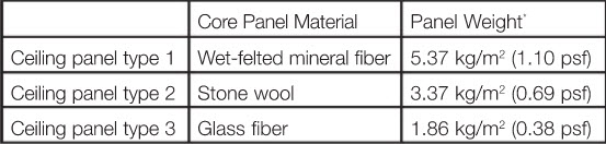
* Panel weights are manufacturer-declared values. Actual weights of the tested panels varied slightly, normally less than the declared values, but this would not affect the results or conclusions.
CAC is a measure of a ceiling panel’s ability to attenuate noise transmitting through a room’s acoustic ceiling, over a partition terminating in height at the level of the suspended ceiling (creating a shared plenum space above the ceiling), and back down through the acoustic ceiling in the adjacent room. It is a double-pass rating as the sound passes through the ceiling two times. While CAC is not applicable directly to this article’s topic of single-pass vertical noise isolation in the presence of a contiguous concrete slab, ratings are provided because industry rules of thumb, even though not technically accurate, include the use of CAC 35+ panels to help with controlling vertical transmission of noise through floor-ceiling assemblies. The CAC ratings of the ceiling panels ranged from 20 to 35, representing the most common performance range used in the industry (CAC ratings for the ceiling panels were based on manufacturer declared values. CAC tests on the panels were not performed).
The noise reduction coefficient (NRC) is the amount of sound absorbed by a surface like an acoustic ceiling panel. It varies between 0.0 (no sound absorption) and 1.0 (a lot of sound absorption). Ceiling panels with higher NRC ratings decrease noise levels and reverberation, making speech in enclosed rooms more intelligible and preventing noise from traveling farther distances in open spaces. The NRC ratings of the ceiling panels ranged from 0.75 to 0.95. This range represents the mid to high range available in the industry. Low-performing panels of NRC 0.70 and below were excluded (the NRC ratings for the ceiling panels were based on manufacturer declared values. NRC tests on the panels were not performed).
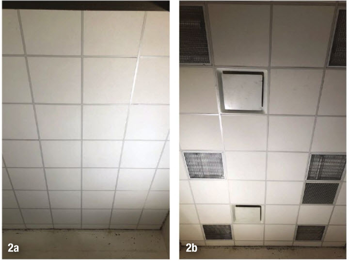
Two series of STC tests were performed. For the first series, all suspension grid modules were filled with only the acoustic ceiling panels (Figure 2a). There were no light fixtures or air distribution devices implemented into the ceiling systems. For the second series of tests, nine ceiling panels were replaced by six recessed light troffers, two plaque-style supply air diffusers, and one eggcrate-style return air grille (Figure 2b). These two series of tests, with and without building service penetrations, were conducted so that any effects of the noise leaking through the penetrations on the overall vertical noise isolation, such as would be the case in real buildings, would be documented.
Color sound mapping
STC, like other acoustic metrics, measures performance of a multi-component, architectural system at different frequencies and then uses a procedure per ASTM E90 to represent the ‘average’ performance with a single number. While the single number metrics are useful for quick comparisons and some decision-making, a lot of beneficial detail is lost. Two assemblies can have the same STC rating and their performance can be perceived quite differently. Therefore, it is wise to also review the transmission loss (TL) performance at third octave band resolution, but even TL is an ‘average’ of how the whole system or assembly is performing.
Sign up for our weekly newsletter
Architectural materials and methods delivered right to your inbox
- CSI News and Notes: CSI Foundation’s construction camp; CSI spring exam; and more
- CSI News and Notes: CSI’s credentials; CSI conference theme; and more
- To be specific – CSI supports young AECO professionals
- CSI News and Notes: CSI’s foundation scholarships, national conference, and Crosswalk
- CSI News and Notes: AI’s impact; CSI 2024 conference, and more
Related Products

Read the Latest Issue