Effects of acoustical ceiling panel type: Vertical sound isolation
Neither STC nor TL can show how specific, individual components are performing relative to the others in the system or assembly. A ‘weak link,’ if present, cannot be identified. For that reason, a commercially available, sound, color-mapping system was used to create maps superimposed over pictures of each architectural test specimen. The color sound maps were created by using specialty software to combine in real-time the acoustic data from a sound intensity probe with its position data from a position tracking device.
Two different types of color sound maps were created. The first type shows sound transmission through the test specimen from a sound source located in the chamber above the floor-ceiling assemblies. The second type of sound map shows sound absorption and reflection off the ceiling systems when the sound source is in the same room below the ceiling systems.
Ceiling sound isolation performance
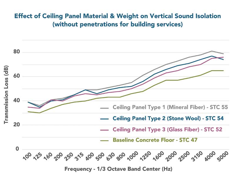
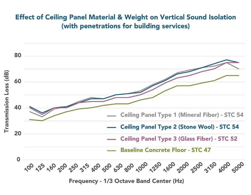
TL and STC results are provided in Figure 3 (no penetrations in the ceilings for building systems devices) and Figure 4 (penetrations in the ceilings for building systems devices). The baseline concrete on steel deck with VCT flooring on top rated STC 47, which is three points below our minimum reference goal of STC 50 based on acoustic standards, guidelines, and rating systems.
Adding an acoustic ceiling to the baseline floor increased the STC rating of the assembly, on average, six-and-a-half STC points. Adding any of the three acoustic ceiling panel types resulted in assembly ratings that were two to five STC points higher than the reference goal of STC 50. The three ceiling panel types varied by only three STC points when there were no penetrations for building systems and differed by only two STC points when the penetrations for lights, supply air, and return air were present.
Figure 5 shows a summary of both types of color sound maps for the three types of ceiling panels. The absorption (NRC) images show top row shows noise reflecting off the ceiling (red and yellow) or being absorbed by the ceiling (blue). The consistent red areas for all three ceiling types are loud noise reflecting off the painted, metal light fixtures, and supply air diffuser. It is important to note the return air grill in all three images is blue because sound is passing through the open return grille, representing perfect absorption, and not reflecting off that part of the ceiling back into the room.
Ceiling panel type 1 (mineral fiber, NRC 0.75) is mostly yellow and red because it is reflecting noise more than absorbing it. Ceiling panel types 2 (stone wool, NRC 0.90) and 3 (glass fiber, NRC 0.95) are mostly blue, like the return air grille, because they are efficiently absorbing and not reflecting the noise. Slightly better absorption can be seen for panel type 3; there is less yellow and more blue.
The isolation (STC) images in Figure 5 show noise leaking through the floor-ceiling assembly. The color maps for the three ceiling panel types are very similar, which is expected since the STC ratings and TL are also alike. The interesting anomaly is the amount of sound leaking thought the return air grille.
The ceiling panels have, essentially, the same absorption characteristics on their topsides (facing up into the plenum above) as they do on their bottom sides (facing down into the room). Since ceiling panel type 1 has a lower absorption rating, noise reflects around inside the plenum more readily, leaking down through the opening at higher levels (red). This is also true, but to a lesser extent for panel type 2 (green/yellow).
The return air grille is only similar to the rest of the ceiling for panel type 3, indicating the noise is being absorbed in the plenum. This difference in noise leaking through the return air grille may produce a localized audible difference for someone directly under the return air grille, but would probably not be audible elsewhere in the room.
Conclusion
Acoustic standards, guidelines, and building rating systems most often require an STC 50 level of isolation between rooms oriented vertically to one another inside education, office, and healthcare facilities. The baseline test shows a 133-mm (5 ¼-in.) thick, 293 kg/m2 (60 psf) concrete slab cannot meet this minimum criterion by itself.
The baseline floor slab is on the thick and heavy side of the normal range for non-residential buildings. Mass law says a doubling of the mass results in a six decibel (dB) increase in noise isolation. It can then be extrapolated approximately to increase the noise isolation of the baseline floor slab from the tested STC 47 to the minimum goal reference of STC 50, the thickness and weight would need to be raised from 133 mm (5 1/4 in.) and 293 kg/m2 (60 psf) to nearly 203 mm (8 in.) and 439 kg/m2 (90 psf).
Sign up for our weekly newsletter
Architectural materials and methods delivered right to your inbox
- CSI News and Notes: CSI Foundation’s construction camp; CSI spring exam; and more
- CSI News and Notes: CSI’s credentials; CSI conference theme; and more
- To be specific – CSI supports young AECO professionals
- CSI News and Notes: CSI’s foundation scholarships, national conference, and Crosswalk
- CSI News and Notes: AI’s impact; CSI 2024 conference, and more


Read the Latest Issue