Reducing overdesign: The structural complexity of shelf angles
By Mark D. Hagel, PhD, P.Eng.
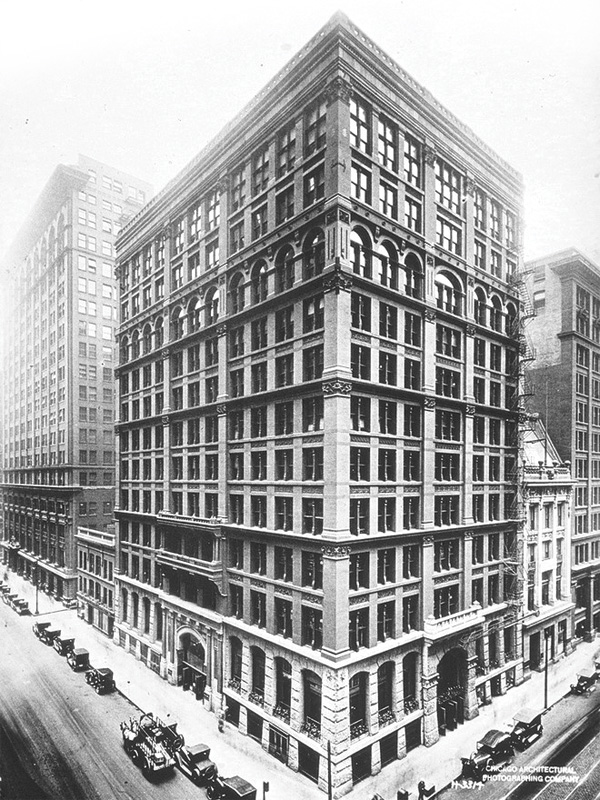
The invention of skeleton frame construction, which creates the building’s primary load-bearing role using a concrete or steel frame “skeleton,” led to the removal of the load-bearing function of masonry in the late 19th century. The first building to use a steel-frame skeleton in North America was the Home Insurance Building in Chicago, completed in 1885. It is also considered the world’s first skyscraper (Figure 1).
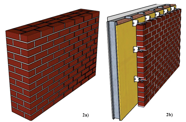
The removal of the load-bearing function of multiple wythes of masonry, as seen in Figure 2a, was accompanied by reducing the masonry to a single wythe of non-load-bearing veneer and a backup wall, as seen in Figure 2b, which required support of its weight using concrete brick ledges or steel shelf angles.
Shelf angle design represents the intersection of masonry design and steel design, and depending on the building’s primary structural system, concrete, steel, or wood design. Therefore, shelf angle design has often been regarded as a “steel” design or a “concrete” design problem rather than a “masonry design” problem. For this reason, very little literature has been published on shelf angle design.
The design of steel shelf angles is not as simple and intuitive as it might first appear. Interactions between the tied masonry veneer and the steel angle and beam behavior from the brick veneer spanning between anchor bolts can be complex to capture with models simple enough for hand calculations. This often leads to oversizing shelf angles and the stand-offs for shelf angles when continuous insulation (c.i.) is used. Overdesign of these steel elements can lead to unnecessary increases in thermal bridging, carbon footprint, and cost of a masonry veneer. This article provides examples and discusses strategies for a more efficient design of steel shelf angles that support the weight of full-bed masonry veneers.
Beam effect and restraining force of masonry ties
The deep beam behavior (action) of the brick veneer spanning between anchor bolts is challenging to capture with simple models for hand calculations. As a result, the beam action of the brick veneer identified by McGinley2 is often ignored when using a simplified hand calculation. The impacts of the masonry ties lead to a statically indeterminate problem and, as such, are frequently overlooked so the design can be reduced to a more easily solved statically determinate problem.
Reviewing the definitions of statically determinate and statically indeterminate structures can help one better understand the problem’s complexity. In 2D, there are three equations of equilibrium. Static equilibrium requires these equations to be equal to zero; in other words, the external forces acting on the structure are resisted by equal and opposite reactions. If the equations were not equal to zero, the structure would move.
A statically determinate structural condition occurs when three unknown reaction forces hold the structure in static equilibrium, and three equilibrium equations are used to determine these forces. Simply put, three equations and three unknowns.
In contrast, with a statically indeterminate structure, there are more reactions than equations of equilibrium. Since there are only three equilibrium equations in 2D, if there are four reactions on a structure, then there are four unknowns and only three equations, creating a statically indeterminate structure with one degree of static indeterminacy. If there were five reactions, the degree of static indeterminacy would be two and so on. Finding a solution for a statically indeterminate structure involves creating additional equations (or relationships) between the forces acting on the structure and the reactions. This is often accomplished by examining the structural deflections/displacements and internal forces within the structure.
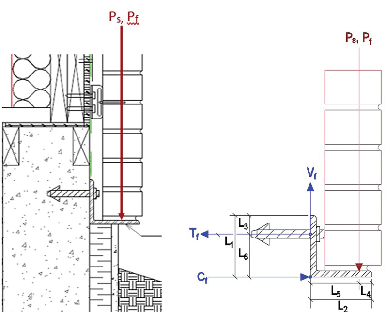
Now that the definitions have been reviewed, the brick veneer system, as illustrated in Figure 3, is typically reduced to a statically determinate structure, as seen in the free body diagram of the system in Figure 4. The simplification of the system by ignoring the restraining force of the ties results in only three unknowns, Tf, Vf, and Cf, which can be easily determined from the equations of equilibrium. However, this can lead to an overestimation of the forces acting on the anchor bolts and increased deflection of the shelf angle, resulting in an unnecessary increase in the size and cost of the shelf angle and an increase in the size and frequency of the anchor bolts. Technical aids that use the statically determinate method to design shelf angles already exist.3 These technical aids conclude that to support the weight of 9 m (30 ft) of traditional 90 mm (3.5 in.) brick veneer, an L102 x 102 x 13 mm (L4 x 4 x 0.5 in.) steel shelf angle is required to meet the maximum deflection of 0.24 mm (0.009 in.) of the L/480 recommended deflection limit. In addition to this, 16 mm (0.6 in.) diameter post-installed anchor bolts spaced at 305 mm (12 in.) on center horizontally would be required to meet the tension and shear forces on the anchor bolts resulting from the weight of the brick veneer.
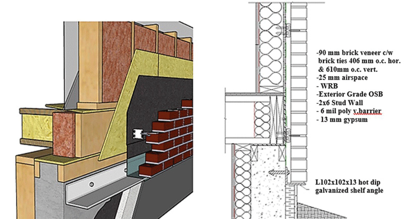
On the other hand, based on field experience of buildings with brick veneers, shelf angles that are half that thickness have been observed to support 9 m (30 ft) of brick veneer without the cracking of mortar joints that can be indicative of excessive movement in brick veneers.
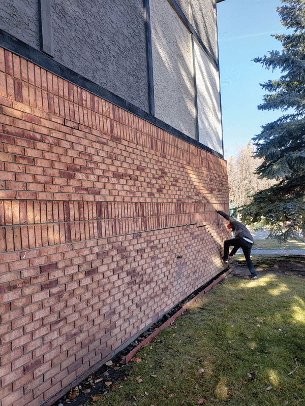
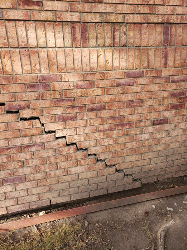
Figure 5a illustrates the impact of both the beam effect and the restraining force of the ties on a brick veneer in situ. In Figure 5a, the approximately 20-ft (6-m) span of shelf angle supporting the veneer has fallen to the ground due to anchor bolt withdrawal on the 30-year-old brick veneer. A horizontal crack developing into step cracking (Figure 5b) has formed due to the absence of support for the weight of the veneer. However, the veneer remains attached to the wall, and no brick units have fallen to the ground. The combined action of the brick veneer appears to create deep beam behavior between the two remaining supports. At the same time, the masonry ties continue to laterally anchor the veneer to the wall.
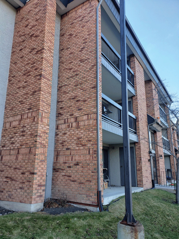
A new design approach is proposed, which more accurately accounts for the interaction between the tied masonry veneer and the shelf angle. The proposed design method more accurately reflects field observations of masonry veneer where an L102 x 102 x 6.4 mm (L4 x 4 x 0.25 in.) can support 7 to 9 m (24 to 30 ft) of 90 mm (3.5 in.) clay brick veneer without evidence of structural distress in brick veneers from excessive deflection that is typically identified by mortar joint cracking. The “as-built” performance of masonry veneers in Figure 6 shows that the deflections and load distribution on a shelf angle are less than what is typically produced with current simplified, statically determinate shelf angle design methods.
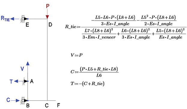
The proposed design method employs the use of the force method in combination with virtual work to solve the one-degree statically indeterminate system that results from the introduction of tie restraining force, RTIE, at the first course of ties as depicted in the free body diagram of the system in Figure 7.
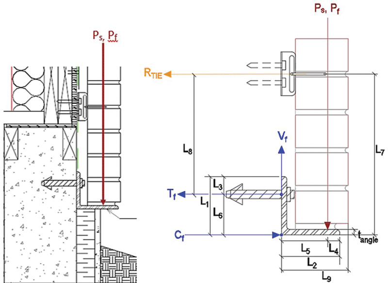
From Figure 8, the following parameters are required to use the force method and virtual work:
P = Unfactored (service load) of masonry veneer and shelf angle (N) per meter
= (20.8 kN/m3) (9.144 m) (0.0921 m) (1 m) + 0.098kN/m = 17,614 N (3,960 lbf)
Pf = Factored load of masonry veneer and shelf angle (N) per meter
= 1.4 (17,614 N) = 24,659 N (5,544 lbf)
RTIE = Reaction force in the brick ties at the first course of ties (kN) per meter
V = Reaction force in the brick ties at the first course of ties (kN) per meter
T = Reaction force in the brick ties at the first course of ties (kN) per meter
C = Reaction force in the brick ties at the first course of ties (kN) per meter
L1 = Vertical leg length (mm)
L2 = Horizontal leg length (mm)
L3 = Vertical distance to the center of the bolt hole = 38 mm (1.4 in.)
L4 = Centroid of brick veneer (typically 45 mm [1.6 in.] for metric modular 90 mm [3.5 mm] brick)
L5 = Eccentricity of veneer load = Air space + (veneer thickness / 2) = (25.4 + 46.1)
= 71.5 mm (2.8 in.)
L6 = L1 – L3 (mm)
L7 = Max 300 mm (11.8 in.) from base support (typically 272 mm [10 in.] + thickness of the shelf angle to meet the joints of the brick coursing)
L8 = Vertical distance between the ties and the center of the bolt hole
L9 = Total length of horizontal leg = Air space + veneer thickness = 25.4 + 92.1
= 117.5 mm (4.6 in.)
In addition to these dimensions, the force method and virtual work require material parameters and assembly dimensions to establish relative stiffnesses. The other values that were required to complete the calculations were:
t_angle = thickness of the horizontal leg of the angle
b = 1,000 mm (1 m of wall design length)
veneer_thick = thickness of the masonry veneer = 92.1 mm (3.6 in.)
V-tie diameter = 2.4 mm (0.09 in.)
f’m = the compressive strength of the masonry veneer
Em = Modulus of Elasticity of the masonry veneer = 850 f’m
Es = Modulus of Elasticity of structural steel = 200,000 MPa
The proof of the following equations is beyond the scope of this paper but can be determined by applying the force method and virtual work to the free body diagram in Figure 8.
For illustration purposes, the proposed method was applied to the design of a shelf angle anchored to a concrete foundation with post-installed anchor bolts that support a 9-m (30-ft) clay brick veneer. The SAP 2000 structural design software created a 3D finite element model using frame and shell elements. The model was used to compare the accuracy of the 2D force method/virtual work hand calculation to a 3D model that captures the interaction of the ties and the brick with the shelf angle. Figure 9 illustrates the 3D finite element model.
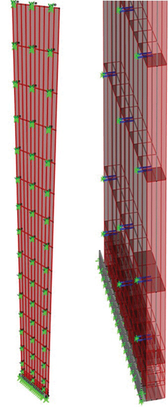
Table 1 compares the tie reaction, anchor bolt and foundation loads using the statically determinate method, the proposed force method/virtual work method and the SAP 2000 3D model. The proposed force method/virtual work method and SAP 2000 have excellent agreement in reaction forces and deflections, with a difference of approximately 3.6 percent and 9.4 percent, respectively. This demonstrates the force method/virtual work method better represents interactions between the tie and shelf angles and brick and shelf angles captured with a 3D finite element model. Table 1 also illustrates the difference in the deflection and loads when using the statically determinate method versus the force method/virtual work method. The difference is approximately 157 percent greater Tf, acting on the anchor bolt, and 572 percent greater deflection in the shelf angle.
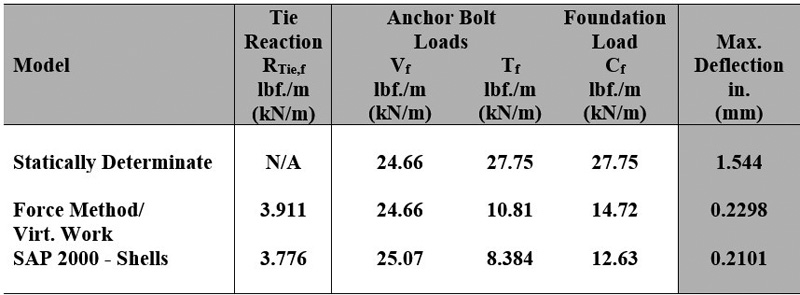
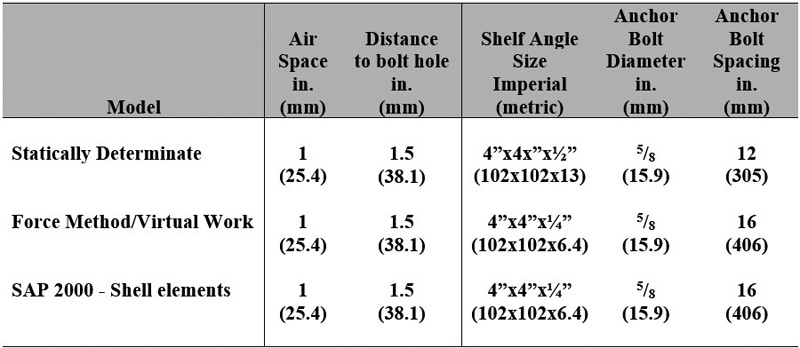
Table 2 demonstrates the design results of the shelf angle, anchor bolt size, and anchor bolt spacing when using the three different design approaches. In Table 2, the shelf angle thickness was reduced from 13 mm (0.5 in.) when using the traditional approach6 to 6.35 mm (0.25 in.) when using the proposed force method and maintained an acceptable deflection less than L/480. In addition, as estimated by the proposed force method, the reduction in forces acting on the anchor bolt translates to an increase in bolt spacing from 305 to 406 mm (12 to 16 in.), reducing the number of anchor bolts required. Depending on the wall length, the cost savings are approximately one percent.
Author’s note: I would like to thank Jordan Kuntz and Lyndsey Jackson of Jackson Masonry Ltd. for their insights from their field experience with shelf angle installations and performance. Without these insights, the results of these findings would not have been possible.
Notes
1 Refer to en.wikipedia.org/wiki/Home_Insurance_Building
2 See the article by McGinley, M., “Design of Shelf Angles for Masonry,” Structure Magazine, structuremag.org/article/design-of-shelf-angles-for-masonry-veneers
3 Review “Shelf-Angle and Brick Ledge Design for Brick Veneer On Mid-Rise Wood-Frame Buildings,” Alberta Masonry Council, Canadian Wood Council, Masonryworx, by Hagel, M.D., Moses, D.., Jonkman, R. (2019). See albertamasonrycouncil.ca/wp-content/uploads/2022/09/Tech-Aid-1-Shelf-Angle-and-Brick-Ledge-November-2019.pdf
Author
Mark D. Hagel, PhD, P.Eng., is the executive director of the Alberta Masonry Council. He holds a bachelor of science in actuarial science and applied mathematics, a bachelor of science in civil engineering, and a doctor of philosophy in civil engineering. Hagel’s fields of expertise include thermal and hygrothermal modelling of building systems, corrosion modelling, Life-cycle Cost Analysis (LCCA), structural analysis and design, and the durability of building components. In 2018, he served on the National Research Council of Canada (NRC) working group that developed the Guideline on Design for Durability of the Building Envelope and in a working group on the CSA-S478-2019 Durability in Buildings. Hagel can be reached at markhagel@albertamasonrycouncil.ca.
Key Takeaways
With masonry reduced to a single, non-load-bearing veneer, steel shelf angles or brick ledges became necessary to support its weight. Shelf angle design combines masonry, steel, and the building’s primary structural material (concrete, wood, or steel) and is often treated as a “steel” or “concrete” design challenge rather than a masonry issue. Consequently, the literature on shelf angle design is limited. Designing steel shelf angles is complex due to interactions between the masonry veneer and structural elements, which are difficult to model by hand, often resulting in overdesign. This can increase thermal bridging, carbon footprint, and costs. This article presents examples and strategies for more efficient shelf angle design to support full-bed masonry veneers.
Sign up for our weekly newsletter
Architectural materials and methods delivered right to your inbox
- CSI News and Notes: CSI Foundation’s construction camp; CSI spring exam; and more
- CSI News and Notes: CSI’s credentials; CSI conference theme; and more
- To be specific – CSI supports young AECO professionals
- CSI News and Notes: CSI’s foundation scholarships, national conference, and Crosswalk
- CSI News and Notes: AI’s impact; CSI 2024 conference, and more
Products


Read the Latest Issue