

by Timothy Ahrenholz
It is an easy mistake to make. For example, when one comes across the R 13 + 7.5 ci wall insulation requirement in the International Energy Conservation Code (IECC) commercial provisions, it can be tempting to just add the two R-values and install R-20.5 rated insulation in the cavity with the assumption being that the same performance can be achieved with fewer steps. However, by employing just R-20.5 cavity insulation, one would be accepting a 16 percent decrease in thermal performance in a wood-framed wall, or a 40 percent decrease in a steel stud wall, when compared to the energy code requirement.
Continuous insulation (ci) and cavity insulation products are both sold with R-value ratings, but the way these two products are used in wall construction means they do not have the same effectiveness. (The article assumes design according to U.S. energy codes. However, the concepts presented here are applicable in all territories, as the underlying science does not change.) Cavity insulation is interrupted by framing members, which let heat through the insulation layer. On the other hand, ci, as the name suggests, is uninterrupted (except at fasteners and service openings, as defined by IECC). So a layer of cavity insulation is less effective than a layer of ci of the same R-value.
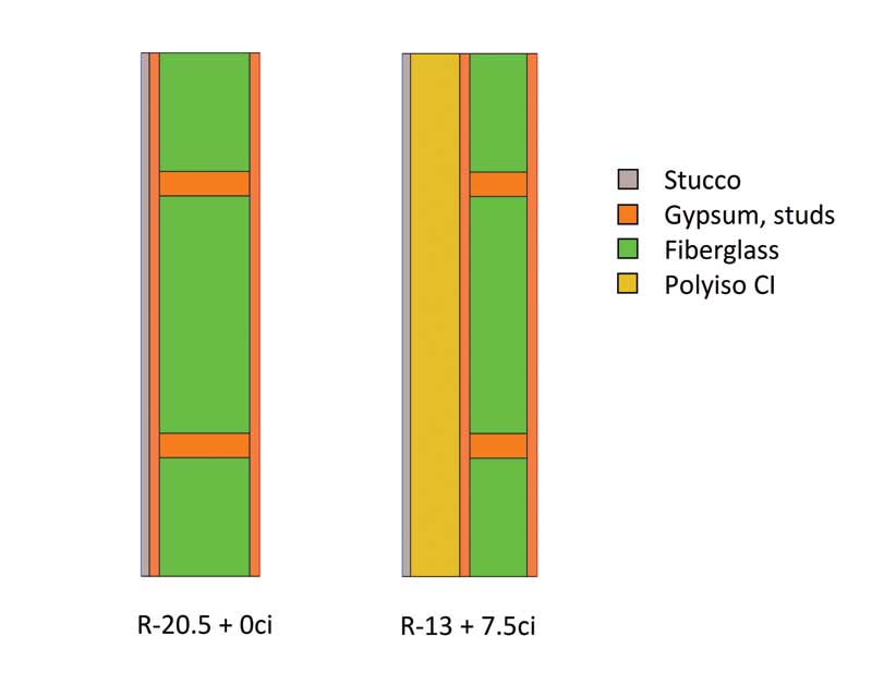
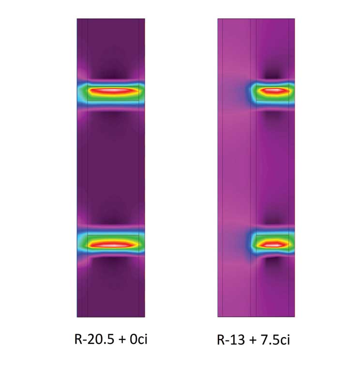
This can easily be seen with thermal modeling software. Figure 1 shows a cross-section of two walls. The left wall is the R-20.5 + 0 ci, and the right is R-13 + 7.5 ci. When these two are subjected to a temperature differential—such as winter outside and room temperature inside—heat flows through the wall from the warm to the cold side. Figure 2 shows the temperature flux, or rate of change, through these walls. As one can see, there is high flux through the wall studs. In the wall without ci, the studs act like a ‘heat highway,’ allowing heat an easy route around the cavity insulation—out of the wall in cold climates and into the wall in hot regions. When ci is added, the highway ends, and heat is forced to slowly seep through the last layer of insulation.
The real math problem of determining a wall assembly’s overall R-value is not nearly so simple as just adding the nominal R-values of the different insulation components (e.g. R 13 + 7.5 ci = R 20.5). Depending on whether wood or steel framing is being employed, different procedures for calculating the assembly R-value of a wall are laid out in the American Society of Heating, Refrigerating and Air-conditioning Engineers’ (ASHRAE’s) 2017 ASHRAE Handbook–Fundamentals and IECC. This article will discuss both the methods. But first, let us look at some of the terms.
Images © Timothy Ahrenholz
R-values and U-factors
In this article, the u-factor (or C-factor) of a component or an assembly refers to its thermal conductance. A u-factor is given in units as W/m2.K (Btu/h-F-sf). One way of understanding these units is the rate of heat transfer (W) through a material with a given u-factor is proportional to the temperature difference on both sides of the material (K) and the surface area available (m2).
The R-value of a component or assembly is the inverse of its u-factor. The R-value describes an object’s thermal resistivity, and the units for R-value are simply the inverse of the u-factor: K.m2/W (sf-F-h/Btu). Therefore, good conductors have low R-values and high u-factors, and good insulators have high R-values and low u-factors. If one knows the R-value of a layer or an assembly, one can find its u-factor by simply calculating the inverse. R-value and u-factor requirements mentioned in this article are taken from IECC.
While any layer of material can be described by its R-value, U.S. energy codes only refer to the R-values of insulation layers in the prescriptive R-value compliance path. Conversely, while any layer or assembly also has a u-factor, energy codes only discuss the u-factors of entire wall assemblies. When this is done, a capital ‘U’ is used. For the remainder of this article, a capital ‘U’ will be employed when discussing assembly U-factors.
If an R-value and a u-factor are just two sides of the same coin, why would the energy codes include both as separate compliance paths? This is because the R-values of individual components like cavity insulation and ci can be easier to work with and understand than assembly U-factors. Many people can picture an R-13 insulation batt whereas a wall assembly with a U-factor of 0.064 is not an intuitive notion. One must delve into some math to understand what this means.
If there are several unbroken layers of different materials forming a wall assembly, the R-value of the entire assembly can be found simply by adding the layers:
Rtotal=R1+R2+R3+…
With u-factors, it is not so simple. Since a u-factor is the inverse of an R-value, to find the overall u-factor, one needs the following equation:
1/utotal =1/u1 +1/u2 +1/u3 +…
(Which, by the way, is the exact same equation. Since a material’s R-value is just the inverse of its u-factor, the author just replaced each R-value with the inverse of the u-factor.) Now one can take the inverse of the entire equation to find the overall u-factor:
utotal=1/(1/u1 +1/u2 +1/u3 +…)
As mentioned earlier, this only applies to the part of a wall with unbroken layers, such as the wall cavity. To account for the framing in the wall, a separate u-factor calculation must be done, and then the two u-factors can be combined to get an overall value for the entire assembly. If one tries to do this using R-values, the answer will be wrong. R-values of different heat flow pathways through an assembly cannot be added together, averaged, or area-weighted to get the overall assembly performance.
Energy codes have tried to make compliance possible without doing any math because the math is not intuitive. This is why they have provided tables listing just a required insulation R-value (and in many cases, an accompanying required ci R-value).
How can this be fair or accurate? It is easy to see a wall’s overall rating depends on a lot more than just the insulation. What about the air films, cladding, structural sheathing, framing, and interior finish? Well, it turns out IECC has assumed the following R-values for all of these layers in a wall in commercial construction:
- exterior air film: R-0.17;
- cladding: stucco, R-0.08;
- sheathing: 16 mm (5/8 in.) gypsum, R-0.56;
- interior finish: 16 mm gypsum, R-0.56; and
- interior air film: R-0.68.
When one uses these assumptions to compute the overall U-factor for the prescriptive R-value wall assemblies, they match right up with the U-factor requirements. To see this correspondence in action, one needs to go through the approved U-factor calculation procedures.

