

Good energy code math
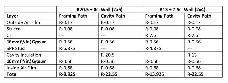
For wood walls, the “parallel path” method is appropriate, (see for example, the “R 20.5 + 0 ci” and “R 13 + 7.5” wall assemblies in Figure 1). This method of calculation can be applied to any combination of ci and cavity insulation required for wood-framed construction (whether commercial or residential). The first step is to determine the R-value for each “path” heat can take through the wall. There are two paths—through the framing (studs and headers) and cavity. In Figure 3, the layers for each path and their R-values are listed. The totals are obtained by summing the R-values for each layer in each path.
One can see while both walls have the same cavity path R-value, the R 13 + 7.5 ci wall has a higher R-value for the framing path (even with a smaller thermal contribution from the thinner 2 x 4 wall framing), thanks to the ci.
The next step is to combine the R-values of the two paths to get an overall value for the entire wall assembly. To do this, the author assumes the wall assemblies are 25 percent framing (21 percent studs and 4 percent headers) and 75 percent cavity by area, which is typical for 406 mm (16 in.) o.c. framing. Then the U-factor for each wall can be obtained with the following formula:
U=ffframing*1/Rframing +ffcavity*1/Rcavity
where ff is the framing factor (25 percent for framing and 75 percent for cavity). Once the U-factor is found, the assembly R-value is just the inverse of the U-factor. This calculation gives us the assembly U-factors and R-values found in
Figure 4.
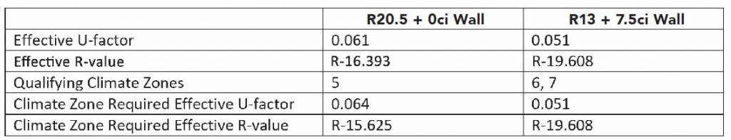
Clearly, with complete energy code math, an R 20.5 + 0 ci wall (effective R-16.393) is not equivalent to an R 13 + 7.5 ci wall (effective R-19.608). Further, it becomes obvious the R 20.5 + 0 ci wall complies with and slightly exceeds the R-value requirements only in climate zone five for IECC residential provisions. On the other hand, the R 13 + 7.5 ci wall complies in climate zones up to seven. It is easy to see the location of the insulation makes a big difference (cavity vs. continuous).
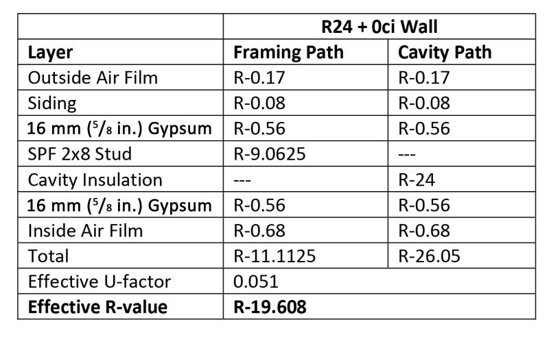
Since the math is covered, let us explore a few more comparisons. For instance, how much cavity insulation would one need to achieve performance equivalent to an R 13 + 7.5 ci wall? As demonstrated in Figure 5, R-24 cavity insulation would be required. In most cases, this would require using 2 x 8 studs, since cavity insulation greater than R-21 is generally thicker than the cavity in a 2 x 6 wall. By using ci, the wall is kept to half the thickness it would be otherwise, saving lots of valuable interior floor space.
The benefits of ci ought to be clear for timber-framed structures, but for cold-formed steel framing, the impact is even more significant. Steel conducts heat more efficiently than wood, so the thermal bridging effect is much more pronounced. In this type of structure, ci is absolutely necessary for adequate performance. The calculation method provided in IECC for commercial steel-framed walls is arguably simpler to implement than the parallel path method for wood walls.

