Energy codes and continuous insulation
by Catherine Howlett | June 1, 2013 11:28 am
 [1]
[1]by J.W. Mollohan, CCPR, CEP, CSI
In light of the federal government’s goal of improving the energy efficiency of new and existing buildings, model energy codes are becoming more stringent. The effort to increase energy efficiency has been further emphasized by initiatives set forth by the 2009 American Recovery and Reinvestment Act’s State Energy Program, and a congressional mandate that all states, must comply, at a minimum, with the American Society of Heating, Refrigerating, and Air-conditioning Engineers (ASHRAE) 90.1, Energy Standard for Buildings Except Low-Rise Residential Buildings, no later than October 18, 2013. The most recent update to ASHRAE 90.1 is the standard on which the 2012 version of the International Energy Conservation Code (IECC) is based. The International Energy Conservation Code (IECC) establishes the requirements for building design, materials, and performance related to energy efficiency. Several successive iterations of IECC (2003, 2006, 2009, and 2012) are currently available for adoption by states and local jurisdictions. Currently, the most widely adopted is the IECC 2009 version. As IECC has become more stringent with each new release, it is crucial to be aware of the version in use where a project is to be located. To help determine this, the International Code Council[2] (ICC) and the Department of Energy[3] (DOE) maintain websites with the most recent adoptions.
Building enclosures and IECC
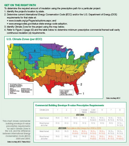
As might be expected, IECC gives considerable attention to the building enclosure’s insulation levels. The code divides the United States into eight Climate Zones and establishes specific requirements for the type, amount, and placement of insulating materials—cavity and continuous—in the exterior enclosure.
For exterior walls, the 2006 IECC requires both insulation in the stud cavity and continuous insulation (ci)—usually either board stock or sprayed polyurethane foam (SPF) outboard of the exterior sheathing for commercial steel-framed wall assemblies in Climate Zones 5 to 8. In 2009, IECC expanded the requirement for ci to include Climate Zones 3 and 4 and increased the required amount of ci in Zones 5 and 6. It now prescribes the use of exterior ci in nearly 90 percent of the country.
New design standards are also emerging, such as ASHRAE 189.1, Standard for the Design of High-performance Green Buildings. This standard includes prescriptive R-value cavity and ci requirements for commercial buildings in all eight Climate Zones. ASHRAE 189.1 has already been adopted by the U.S. Army Corps of Engineers (USACE) for federal and military construction.
The IECC gives design professionals multiple options to satisfy code requirements. Whole building modeling allows the user to examine potential solutions. The design professional may also either elect a prescriptive or performance path for determining the necessary amount of insulation in exterior wall assemblies.
The prescriptive method relies on the R-value of only the insulation materials and matches those values to predetermined insulation requirements for various wall types and Climate Zones. For example, the IECC establishes minimum prescriptive R-value for both cavity and exterior ci for steel and wood-framed wall construction based on each Climate Zone. If these values are met, no further analysis or calculations are required.
The performance method is slightly more complicated, but allows the design professional the flexibility to use knowledge and experience in creating the most appropriate solution to the clients’ needs, while still meeting code requirements. This method’s calculations are based on the wall’s U-factor (the fractional inverse of R-value [i.e. an R-value of 13 equates to a U-factor of 1/13, expressed by the decimal 0.0769]) and takes into account the thermal resistance rating of not just the insulation materials, but also all the wall assembly components, analyzed together to meet the Climate Zone’s thermal performance requirement.
The prescriptive and performance methods, though taking different approaches, generally produce similar results in the amount of both cavity and continuous insulation required for a particular Climate Zone and wall type. Perhaps a little insight into some of the problems the modern energy codes are attempting to solve may help when deciding which path best serves a project’s needs.
Making walls more efficient
The updates to the building energy codes are intended to address several critical issues with traditional building methods, specifically thermal bridging and the relative ineffectiveness of cavity insulation.
A typical framed wall assembly used wood or steel studs with some form of cavity insulation—usually fiberglass batts. Although economical, this assembly is thermally inefficient because only the cavities are insulated. The framing separates the insulation into non-continuous pockets and allows energy in the form of heat to conduct through the studs, bypassing the insulation and creating a condition known as ‘thermal bridging.’ Thermal bridges, along with convective losses, can reduce the effective performance of cavity insulation in steel-framed wall assemblies by 50 percent or more.
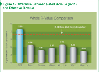
Among the independent resources reinforcing the reality of energy loss and reduced effective cavity insulation values due to thermal bridging, is a study conducted at the Department of Energy’s (DOE’s) Oak Ridge National Laboratory (ORNL). Performed to investigate the difference between the rated R-values of common wall designs and their tested effective value, the study evaluated “whole wall” construction, including materials and framing discontinuities such as transition details at windows, doors, roofs, floor lines, and typical wall-accessory penetrations. Though the claddings tested varied, all were mounted to the constant of a nominal 89-mm (3 1⁄2-in.) steel-framed wall assembly with 12.7-mm (1⁄2-in.) gypsum interior wallboard, R-11 fiberglass batts, and 12.7-mm glass-mat faced gypsum exterior sheathing. The claddings compared included:
- exterior insulation and finish system (EIFS);
- brick veneer;
- glass;
- stone and cast-stone masonry;
- stucco; and
- wood siding.
 [4]
[4]Data courtesy Oak Ridge National Library (ORNL)
Results of the study show a significant decrease between the rated and the effective R-values of the various walls using only cavity insulation. For example, Figure 1 shows although built on an R-11 assembly, the tested effective R-value of the brick veneer assembly was only R-6.98. This degradation of the perceived insulation value of the assembly is a direct result of thermal bridging. The study confirmed the dramatic negative effects of thermal bridging in assemblies that only use cavity insulation.
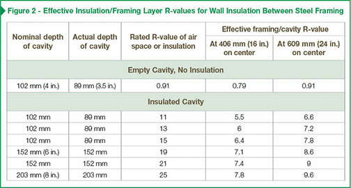
Tests such as ORNL’s are further substantiated by ASHRAE 90.1, specifically the standard’s Table A9.2B, which looks at the perceived versus the effective R-values of fiberglass batt insulation in steel-framed construction, and is used by mechanical engineers to determine the actual energy performance of exterior wall assemblies for the proper sizing of HVAC equipment.
The table in Figure 2 shows a perceived R-11 steel-framed wall assembly with studs at 406 mm (16 in.) on center (oc)—the underlying assembly used in the ORNL study walls—in reality has only the effective R-value of 5.5. This is a reduction of 50 percent from the rated value of its constituent insulation. Further, the ASHRAE table demonstrates the futility of attempting to overcome poor performance by increasing stud depth and quantity of cavity insulation. Moving from an R-13 to an R-19 with the perceived increase of R-6, in fact gains only an effective increase of R-1.1.
 [5]
[5]Data courtesy ASHRAE 90.1, Table A9.2B
Concrete masonry units (CMUs) are also widely used in structural exterior wall construction. CMU is a highly conductive (low R-value) material. Insulating CMU walls generally requires adding insulation in between furring channels, which are required for cladding attachment to the exterior, or the gypsum wallboard to the interior. However, the furring re-creates the repeating thermal breaks, again allowing heat flow to essentially bypass the insulated portions and does not meet the ASHRAE definition of continuous insulation.
As seen, cavity insulation alone provides little thermal benefit when undermined by thermal bridging. R-value reduction due to thermal bridging is not an indictment of cavity insulations. Even the most efficient insulation materials cannot function to their fullest potential when interrupted every 406 mm oc. The surest method of overcoming these energy-sapping hazards, now codified in IECC and ASHRAE 189.1, is the application of a layer of continuous insulation to the exterior wall.
Further issues
Dewpoint and related condensation is another critical issue in all modern wall assemblies. Dewpoint is defined as the temperature and pressure at which the humidity in moisture-laden air potentially condenses from vapor into liquid form. This gaseous moisture can travel from inside a heated building to a cold exterior in cold climates and/or from a hot exterior to a cooled interior in warmer climates. Condensation will occur when the moisture-laden air contacts surfaces that are below the dewpoint temperature.
It follows then, as required by the IECC, thermally isolating the wall by the addition of exterior continuous insulation will greatly improve the wall’s ability to tolerate moisture vapor. Since warmer air can hold more water in vapor form, by adding insulation on the exterior, the temperature of the wall is increased (for heating seasons), thereby reducing the possibility of condensation occurring within the structural portion of the assembly.
As stated, dewpoint is wall- and climate-dependent. Its potential can only be fully identified through some form of water vapor transmission analysis such as the German heat and moisture thermodynamics calculator, Wärme Und Feuchte Instationär (WUFI). Reputable manufacturers of insulation materials and thermal claddings will generally perform these calculations for the design and construction professional as a complimentary service.
 [6]
[6]Data courtesy ASHRAE 189.1
A comprehensive solution
Architects, constructors, and building owners today face many complex challenges, including the need to design in conformance with these rapidly changing energy codes. All parties are challenged to cost-effectively meet the latest mandates while maintaining aesthetic diversity in both new and retrofit construction.
By far, the most effective way to address these building enclosure challenges is to incorporate ci into the exterior wall assembly. According to the previously cited ORNL study, the use of exterior ci can translate into a 20 to 30 percent improvement in envelope energy efficiency.
The only cladding included in the study that incorporated an integral ci component was EIFS. With its higher performing, uninterrupted insulation, the EIFS exceeded the baseline wall assembly, testing at 84 percent more energy efficient than a non-ci insulated option. That is not to say that most of the other walls tested cannot be greatly enhanced by the addition of a ci component.
Extruded polystyrene (XPS) and polyisocyanurate (polyiso) boards behind brick veneer and stone masonry are also common additions. Multiple permutations of continuously insulated stucco have been introduced. However there are significant ramifications to the modification of these assemblies.
Since the heavier claddings are cantilevered farther off the structural line by the addition of ci, they require a corresponding increase in structural steel, as well as additional foundation support.
As we move toward the goal of net-zero energy consumption, the codes require additional insulation exacerbating these difficulties. Adding more than 76.2 mm (3 in.) of ci behind a brick or stone veneer may require re-engineering of the structural elements, driving up material and labor costs, as well as time spent onsite.
Another hotly debated issue arises as modifications are made to the myriad exterior wall assemblies and claddings. The inclusion of foam plastic insulation components such as EPS, XPS, SPF, and polyisocyanurates subject the assembly to the stringent requirements of the National Fire Protection Association (NFPA) 285, Approval for Wall Assemblies Using Foam Plastic Insulation. This test requires the specified and installed assembly exactly replicate the tested assembly. Subject to interpretation by local code officials, the smallest variation (including adaptations to accommodate the addition of now-required ci), may violate the standard and subject the manufacturer(s), designers, engineers, and/or owners to additional delays and costs for retesting of the modified assembly.
One of the simplest and most cost-effective ways to add ci to the exterior of a traditional wall assembly is through the use of EIFS. A typical assembly with drainage is composed of the following layers or components:
- fluid-applied flashing;
- a continuous fluid-applied air and water-resistive barrier;
- vertically notch-troweled adhesive/drainage plane; and
- exterior ci (either EPS or XPS), fiberglass mesh-reinforced base coat, and integrally colored textured finish.
EIFS are non-structural in nature and offer ci as an integral component of the system, which may be adhesively attached to an underlying wall assembly minimizing thermal bridging. During construction and throughout the lifetime of the building, these assemblies can deliver measurable benefits and significant return on investment (ROI). They can be:
- lightweight compared to traditional claddings, requiring less concrete and structural steel to support the weight of the wall and reducing material costs;
- installed by a single, trained subcontractor, reducing construction time and labor costs;
- engineered, tested, and fully warranted by the manufacturer; and
- require minimal maintenance over the lifetime of the building, reducing associated costs.
From an aesthetic perspective, EIFS also offer unlimited architectural design flexibility. In addition to a variety of plaster-like finishes, EIFS can also resemble brick, limestone, granite, and metal. Shapes and reveals can also be customized to complement any architectural style.
Additionally, the material can be a contributing factor to Leadership in Energy and Environmental Design (LEED) credits in categories such as:
- Materials and Resources (MR): Credit 1.1, Building Reuse, Credit 2, Construction Waste Management, Credit 4, Recycled Content, and Credit 5, Regional Materials;
- Indoor Environmental Quality (IEQ): Credit 7.1, Thermal Comfort: Design; and
- Energy and Atmosphere (EA): Credit 1, Optimized Energy Performance.
Conclusion
As energy becomes dearer, the building energy codes will continue to become more stringent. Knowledge of the evolving requirements will be essential to all parties involved in the construction process. The use of EIFS can meet the codes, greatly reduce the complexity of the exterior wall component of many projects, and save time, money, and considerable scheduling challenges along the way.
 [7]
[7]
J.W. Mollohan, CCPR, CEP, CSI, has 30 years of experience in the design and construction industry, and is currently a strategic markets manager at Dryvit Systems Inc. He is a member of the Leadership Team of the Kansas City Building Enclosure Council (BEC), immediate past-president of the Kansas City Chapter of the Construction Specifications Institute (CSI) and chair of CSI’s national membership committee. Mollohan can be reached at jw.mollohan@dryvit.com[8].
- [Image]: http://www.constructionspecifier.com/wp-content/uploads/2015/11/Insulation_Streets-of-Woodfield.jpg
- International Code Council: http://www.iccsafe.org/gr/pages/adoptions.aspx
- Department of Energy: http://www.energycodes.gov/status-state-energy-code-adoption
- [Image]: http://www.constructionspecifier.com/wp-content/uploads/2013/06/insulation-Fig1.jpg
- [Image]: http://www.constructionspecifier.com/wp-content/uploads/2013/06/insulation-Figure2.jpg
- [Image]: http://www.constructionspecifier.com/wp-content/uploads/2013/06/insulation-ASHRAE-189.1.jpg
- [Image]: http://www.constructionspecifier.com/wp-content/uploads/2013/06/insulation_theRightPath.jpg
- jw.mollohan@dryvit.com: mailto:jw.mollohan@dryvit.com
Source URL: https://www.constructionspecifier.com/energy-codes-and-continuous-insulation/