Design
As discussed earlier, many of the CFRP manufacturers offer design services. Consequently, communications between the EOR and the MD become critical. Information about deficit shear capacity, existing concrete strength, reinforcement details, and cross-sectional dimensions of the members are commonly required by the MD. The reported dimensions must consider construction tolerances. The EOR should also clarify whether the reported required strength is the nominal or design (factored) strength.
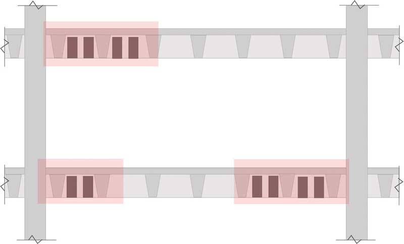
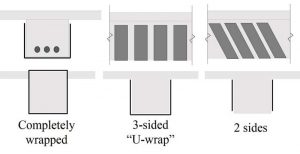
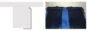
Shear strengthening using CFRP may be achieved by providing vertical or diagonal strips along the sides of a member similar to the placement of stirrups as shown in Figure 1. Typically, the CFRP sheet wraps the sides and bottom surfaces of the member to form a U-shaped wrap (U-wrap). In repair of concrete girders, maintaining uniform spacing of CFRP strips may not be possible where secondary members frame into the girder. Such information should also be communicated to the MD. Figure 2 shows an elevation of a typical girder and joist spacing.
A frequent challenge is accessibility of the concrete surface for installation of the CFRP wraps. For example, the girders along ramp intersections in a parking garage are typically accessible from one side only; the adjoining up-ramp blocks access to the opposite side of the girder. Therefore, the typical U-wrap configuration would not be feasible.
An alternative solution is applying the CFRP wraps to one side only, but this results in reduced bond surface of the CFRP. In compromise, anchorage is required to help develop higher strains in the CFRP sheets. Providing adequate bond between the CFRP and concrete is more efficient than providing a greater number of CFRP sheets to achieve a certain strength. A common failure pattern in experiments of CFRP-wrapped concrete is debonding of the plies from the concrete. (For more, refer to the 2017 paper, “Use of Carbon Fiber Reinforced Polymer (CFRP) with CFRP Anchors for Shear-Strengthening and Design Recommendations/Quality Control Procedures for CFRP Anchors” by J. O. Jirsa, W. M. Ghannoum, C. Kim, W. Sun, W. A. Shekarchi, N. K. Alotaibi, and H. Wang for the Center for Transportation Research, University of Texas at Austin.)
Anchorage may be achieved through mechanical fasteners, FRP stirrups, and fiber and near-surface mounted (NSM) anchors, as discussed in ACI 440.2R. To provide adequate shear capacity to the intersecting ramp girders, the CFRP sheets can be anchored as shown in Figure 3. This method resembles the NSM anchorage discussed in ACI 440.2R. It is critical the number of anchors and location of the anchors are clarified with the MD, who may specify a typical anchorage method. One-sided wraps would require anchorage at both top and bottom, unless noted. Alternatively, the bottom of the wrap may be extended under the girder or by other methods as specified by the manufacturer.
By the end of the delegated design phase, the MD should provide the required width of CFRP strips, number of plies, and spacing, as well as the configuration of the wrap and specific requirements for anchorage or development length. It is recommended the contract documents identify the required submittals to be obtained by the contractor from the MD. By doing so, the EOR communicates the intent of the delegated design to the contractor. Note ACI 440.8, Specification for Carbon and Glass Fiber-Reinforced Polymer Materials Made by Wet Layup for External Strengthening of Concrete and Masonry Structures, covers the requirements for CFRP wet layup installation.
The EOR should request a copy of the design calculations, and understand and agree with them. One shortcoming of ACI 440.2R is it does not address factors associated with one-sided wraps, which are sometimes the only practical solution due to site obstructions. Therefore, engineering judgement becomes critical in evaluating the assumptions considered by the MD. In addition to the strength reduction factor, ACI 440.2R specifies FRP strength reduction factor based on the variability in experimental results. This factor varies based on the configuration of the wrap (fully-wrapped vs. U-wrap or two-sided wraps).
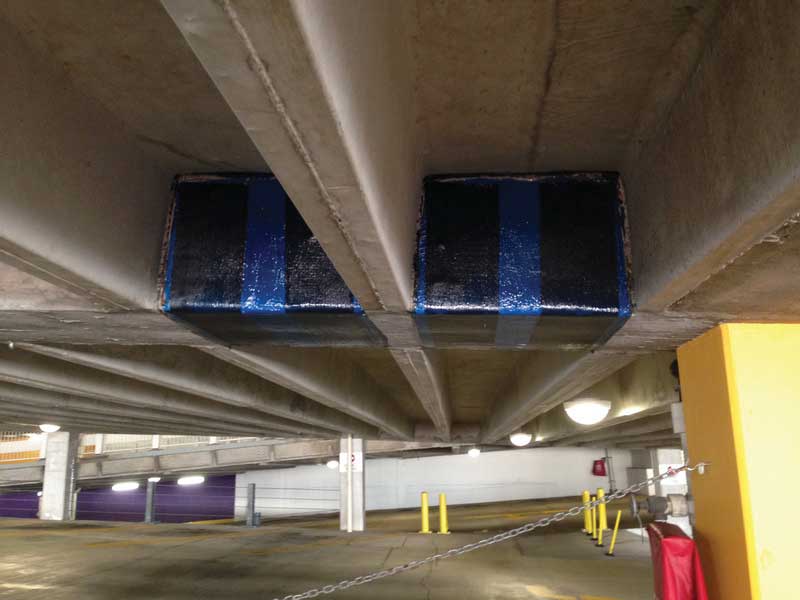
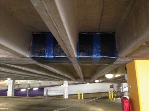
The EOR must also ensure the recommended design (strip width and spacing) are practical and systematic in consideration of the construction. For example, it would save time for the contractor if all CFRP strips were designed to be 250 mm (10 in.) wide, which can be easily achieved by cutting a 500-mm (20-in.) roll in half. Where possible, specifying uniform spacing in each location can eliminate errors in construction and monitoring. Figure 4 shows the uniform strip width and spacing at a repaired location.


