Ensuring reliability and efficiency for data center design
by Katie Daniel | November 3, 2017 10:44 am
 [1]
[1]by David Brender, PE
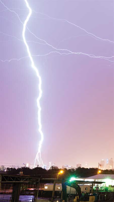
As the world moves away from paper material, data centers are essential in storing credit card information, various confidential government materials, and other sensitive information that could potentially put an individual or country at risk. Without proper protection systems in place, these critical facilities expose themselves to Mother Nature’s disastrous effects, which could result in expensive downtime and even data loss. Such crises are never expected, but by installing code-exceeding lightning protection and grounding systems, their occurrence can be greatly mitigated and, in some cases, even prevented.
Since severe weather systems cannot be prodded or manipulated, all facilities run the risk of potentially experiencing a direct lightning hit to their primary power line, building, or other electrical equipment. Fortunately, simple and inexpensive techniques—such as proper electrical and grounding systems—can help prevent or reduce problems.
Center design and lightning protection
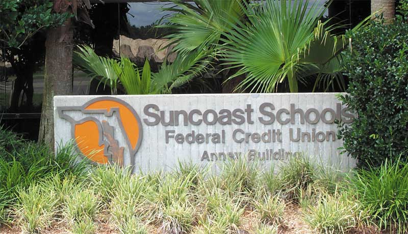
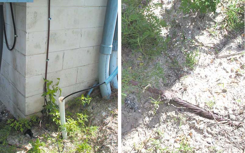
A direct lightning hit to a data center’s primary power line can potentially cause data loss, downtime, and expensive repairs. However, if the center has a proper grounding system in place, it will continue functioning without interruption, much like Suncoast Schools Federal Credit Union’s data center located near Tampa, Florida.
The bank’s data center is situated in one of the most lightning-prone cities in the United States. To minimize the risk of downtime or data loss, the bank installed a low-resistance, heavy-gage copper grounding system (under 5 ohms), along with a multilayer surge protection. The investment in a proper protection system paid off on the day lightning struck the center.
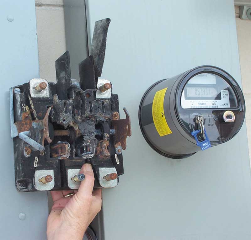
The bolt hit the center’s 480-V service entrance cable and destroyed the electric meter and socket, but did no other damage. The grounding system, coupled with the cascading transient voltage surge suppressors (TVSS), directed the lightning surge to the earth before it could do any damage downstream. No one in the center even knew the facility had been hit.
The added protection prevented the bank’s expensive data-processing equipment and important financial data from being damaged or destroyed. No equipment damage, no downtime. With proper grounding and lightning protection systems in place, facility managers can ensure uninterrupted uptime for their tenants.
The purpose of a lightning protection system is to provide a low-impedance, easy path through which the lightning energy can flow. These systems neither attract lightning to structures, nor do they repel it. Rather, they intercept the lightning and channel the energy onto a low-resistance path. Lightning systems and surge-protection devices must be connected to a low-impedance ground electrode system to operate. The grounding resistance should be checked upon installation and annually or semiannually thereafter, depending on experience encountered. Five ohms to earth or less is recommended. Since the use of the building framing steel as a down conductor introduces the lightning energy directly to the interior of the building—where it can damage the data or equipment or couple to the electrical wiring—separate copper conductors insulated from the structural steel are recommended as down conductors.
To work effectively, the entire grounding system needs to be properly designed using listed connectors and corrosion-resistant materials. Copper and its alloys are the most-common materials used for reducing power quality problems. Unlike other materials, copper avoids oxidation complications, allows for superior reliability, and provides corrosion resistance at connections. (Other material options include galvanized steel and, for certain soil chemistries, stainless steel. However, the latter is expensive for this application and not particularly common.)
 [2]
[2]Photos courtesy Copper Development Association
Fully redundant electrical systems
Copper also plays a role in the reliability of the Involta data center in Boise, Idaho; the 2915-m2 (31,400-sf) facility has an all-copper wiring and interior bonding and grounding systems. There is one grounding system with uninterrupted electrical continuity throughout the entire center. All of the center’s electrical equipment, including information technology (IT) equipment, operates at a single, uniform ground potential.
Constant expansion and contraction under ‘load/no-load’ conditions can cause non-copper materials to creep—a process resulting in the loosening of terminations. In turn, loose connections tend to heat up, and will sometimes arc dangerously. Copper may cost a little more initially, but its low maintenance and reliability make it cost-comparative to other common materials over time.
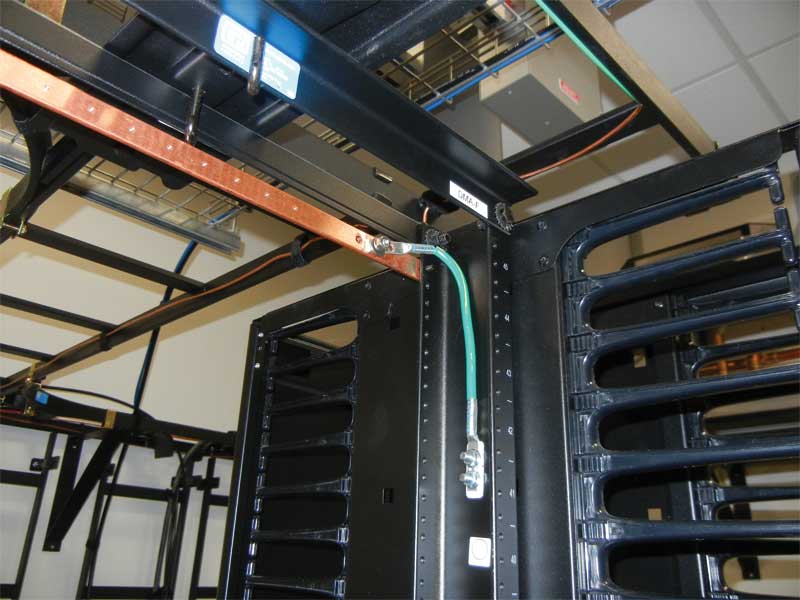
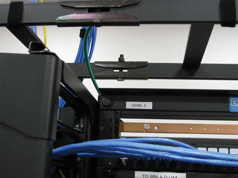
Power distribution buses are used in the center’s carrier rooms, where servers for Internet service providers (ISPs), networking, and several other communications companies are installed. Bonding conductors are routed to traditional copper grounding bars attached to rack frames. The racks themselves are bonded to copper buses with heavy-gage copper cables, and then to the master ground bus (MGB). Heavy-gage grounding conductors connect power distribution systems with copper grounding bars placed at convenient locations in the data rooms and mechanical spine.
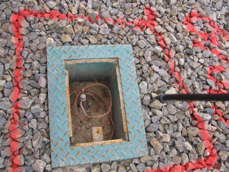
An AWG 2/0 buried bare copper ring completely surrounds the center. Bonded to the ring at periodic intervals are 3 m x 19-mm (10 ft x ¾-in.) copper-clad grounding electrodes. Access ports along the ring allow for inspection of such items as lug tightness and ground resistance. All the facility’s electrical and lighting systems are connected to this ring. Mechanical equipment, water, gas, and telephone systems are also properly grounded and do not share branch circuits with IT systems.
Also bonded to the ring are copper down-conductors from the rooftop lightning protection system. They consist of interconnected, regular-spaced termination devices (i.e. lightning or Franklin rods) mounted along the roof’s periphery. This system fully protects the center from expensive damage, downtime, and data loss.
 [3]
[3]Redundancy also helps Involta maintain 100 percent uptime for its tenants. In data center terms, reliability means having built-in redundancy—usually duplicate equipment and/or systems for any mission-critical need. The center is equipped with a pair of 1-MW emergency generators serving its two power feeds. The generators are load-tested monthly and no-load-tested weekly, with results carefully documented. Should there be a utility failure and one generator goes down, the backup generator can support the critical load. Backing up the power feeds to data halls are two 500-kW uninterruptible-power-supply (UPS) units equipped with sufficient battery capacity to keep the critical load operating for 50 minutes based on the current critical load. One beneficial feature of a dual system is it enables personnel to shut down either feed if the other one requires maintenance or repair. Equipment on the system then remains completely operational, and the center’s 100 percent uptime is preserved.
Since systems can degrade over time, connections loosen, contact resistances rise, and loads can change—these may produce unexpected effects. Grounding connections and resistance should be checked on a fixed schedule and changes investigated as needed. Power quality should be monitored to ensure clean waveforms and voltage stability. Emergency generators and UPS units should be periodically tested. As the saying goes, you do not get what you expect—you only get what you inspect.
 [4]
[4]Helpful power quality techniques
In cases where power quality problems are encountered in an existing facility, careful study will be necessary to determine the best course of action. Solutions may be as simple as moving some loads between branch circuits or minor rewiring. In difficult cases, professional engineering assistance is recommended. The Copper Development Association (CDA) also suggests the following steps to help prevent power quality problems from occurring.
Copper conductors
There is less risk of failures related to power quality because of copper’s superior connectablity. Poor-quality connections are a major concern, especially when multiple contractors of unknown workmanship modify the system. This is where all-copper wiring excels over other materials.
Exterior ground ring
The use of an outside copper ground ring, sometimes combined with vertical electrodes, helps achieve low impedance from the building’s grounding system to the earth itself, and a convenient means of connecting various grounds leading from the building.
Segregation of sensitive loads
Power-sensitive equipment should be placed on separate dedicated branch circuits emanating from separate panel boards, fed from separate feeders back to the main service entrance. The neutrals and grounding conductors also need to be kept separate. One should never mix sensitive equipment with standard loads, motor loads, or outdoor loads.
Limited number of outlets per circuit
Three to six outlets per circuit maximum is recommended instead of the 13 permitted by the National Electrical Code (NEC) on a 20-amp circuit. This will minimize the amount and variety of sensitive equipment sharing circuitry. It tends to reduce voltage drop, decrease the chance for interaction, and leave some room for later growth or equipment changes.
 [5]
[5]Conduit as a ground path
A metal conduit, properly grounded, provides shielding of the conductors from radiofrequency (RF) energy. However, one should not omit the grounding conductor (i.e. green insulated copper wire), irrespective of the conduit material, as it is needed for safety, as well as assurance of a continuous, low-impedance path to ground. The grounding conductor should be at least as large as the phase conductors and is run inside the metal conduit, rather than outside.
Voltage drop
Although NEC allows up to a five percent voltage drop on the combined branch and feeder circuits, recommended practice is to design for no more than a three percent voltage drop at full load on the combined circuits feeding sensitive equipment. This means conductor gages should often be larger than required by code minimums. However, a side benefit of larger conductor gage is larger conductors frequently save enough energy, due to their lower resistance, to compensate for higher initial cost, with a short payback.
Depth of grounding
Where there is insufficient real estate with which to work, or under conditions of unusually high ground resistivity, deep grounds may be required. Long copper ground rods, sometimes hundreds of feet long, in bored holes, are not uncommon in some cases. (To achieve 5 ohms, lengths of 15 to 30 m [50 to 100 ft] can be required. Case studies are available at www.copper.org/applications/electrical/pq[6].)
 [7]
[7]Surge and lightning protection
Lightning protection systems provide a low-impedance, easy path for the lightning energy to flow. This maximizes current in the lightning protection system, but it also minimizes current to the sensitive equipment. Lightning systems and surge protection devices must be connected to a low-impedance grounding electrode system to operate properly. As mentioned, the grounding resistance should be checked upon installation, and again periodically—annually or semiannually, depending on experience encountered. Five ohms to earth or less is recommended by Institute of Electrical and Electronics Engineers (IEEE) and others.
The ‘clean ground’ myth
Installers sometimes request a so-called ‘clean ground’ for their equipment, in the mistaken belief it does not need to be connected to other equipment within the environs. This practice is dangerous, as it establishes multiple paths to ground, thus using the earth as a conductor. In cases like these, adjacent equipment may be at different voltages. Also, by having separate grounds, there may be a shock hazard. All equipment must be connected to one common grounding system.
 [8]
[8]The answer
The best time to examine an existing grounding system (or install a new one) is before disaster strikes. If there are any doubts about the wiring in a specific facility, it is critical to call a competent licensed electrician or a power quality professional for assistance.
With proper bonding and grounding systems in place, it is unlikely a data center will experience any residual storm effects. The best way to safeguard against electrical hazards is to have a licensed professional electrician install, inspect, and—if necessary—upgrade the wiring. The average additional cost to install an enhanced electrical distribution system—designed to the currently recommended practice versus a ‘standard’ one—has been estimated at one to two percent of the cost of construction. Due to the precautionary systems put in place, data centers should be able to ensure uninterrupted uptime to their customers. (To learn more about proper grounding or lightning protection systems for data centers, visit copper.org[9]. CDA also offers seminars on this and other subjects to contractors, inspectors, engineers, and other groups. For more information, visit www.copper.org/electricalseminars[10].)
David Brender, PE, is the national program manager for the Copper Development Association (CDA) in New York City. His duties involve directing and managing CDA’s Building Wire and Power Quality initiatives, research activities, and work related to the National Electrical Code (NEC) and (IEEE) activities. Brender has authored numerous magazine articles and white papers on grounding and other power quality subjects, and is a member of Panel 5 of the National Electrical Code. He is a licensed Professional Engineer in New Jersey, New York, and Pennsylvania, and is a Certified Power Quality Professional from the Association of Energy Engineers. Brender can be reached at david.brender@copperalliance.us[11].
- [Image]: https://www.constructionspecifier.com/wp-content/uploads/2017/11/bigstock-198353833.jpg
- [Image]: https://www.constructionspecifier.com/wp-content/uploads/2017/11/Figure-1-copper.jpg
- [Image]: https://www.constructionspecifier.com/wp-content/uploads/2017/11/Figure-3-copper.jpg
- [Image]: https://www.constructionspecifier.com/wp-content/uploads/2017/11/Figure-5-copper.jpg
- [Image]: https://www.constructionspecifier.com/wp-content/uploads/2017/11/edit1.jpg
- www.copper.org/applications/electrical/pq: http://www.copper.org/applications/electrical/pq
- [Image]: https://www.constructionspecifier.com/wp-content/uploads/2017/11/Figure-8-copper.jpg
- [Image]: https://www.constructionspecifier.com/wp-content/uploads/2017/11/Figure-6-copper.jpg
- copper.org: http://copper.org
- www.copper.org/electricalseminars: http://www.copper.org/electricalseminars
- david.brender@copperalliance.us: mailto:david.brender@copperalliance.us
Source URL: https://www.constructionspecifier.com/ensuring-reliability-efficiency-data-center-design/