Essential structural considerations in roof design
by arslan_ahmed | April 20, 2023 8:00 pm
 [1]
[1]By David Thompson, PE
Design professionals often work in isolation, with each discipline (architectural, structural, mechanical, and electrical) working exclusively on their own discipline, and only getting together after they have completed most of their individual design contribution to coordinate dimensions. This approach frequently limits the amount of detailed information exchanged between the design team until the final stages of the project. Crucial data is unintentionally missed, and this can significantly affect the structural design of roof systems.
Anticipating what the structural engineer needs to consider when making design choices and how the other disciplines influence these decisions (many times without realizing it) will be addressed in this article, as well as:
- How rain, snow, and wind loads are handled in the U.S. and Canada.
- Historical context that influences how different loads are estimated.
- Impact of decisions made by the project team which affect structural engineering outcomes.
- Influences of product limitations and load capacities from manufacturers.
- Information that must be included in contract structural specifications.
Weather
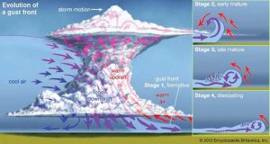
Roofs prevent weather from affecting the lives of people inside a building. Extreme weather events occur either when tropical storms, or for the interior of the continental U.S., large-scale system (cold or warm front), short-lived storms, or snow squalls move through an area. Short-lived storms can develop into thunderstorms, hailstorms, or tornadoes. Thunderstorms can cause extreme wind events, hailstorms, and/or tornadoes.
Codes and standards
In the U.S., building codes are a municipal responsibility. Most municipalities do not want the responsibility of developing their own code, so they rely either on the state government to develop building codes or the International Code Council (ICC). The ICC is a non-profit association focused on building safety solutions. The council is responsible for producing the International Building Code (IBC) as well. Most of the states use the IBC as a basis for their state building codes. The IBC has adopted significant portions the American Society of Civil Engineering’s Standard, ASCE-7, Minimum Design Loads for Buildings and Other Structures for the structural loading requirements of buildings.
 [2]
[2]However, each jurisdiction having its own building code led to situations where different municipalities used different editions of the IBC. Currently:
- Four states have adopted IBC 2021, ASCE-7-16.
- 26 states have adopted IBC 2018, ASCE-7-16.
- 16 states have adopted IBC 2015, ASCE-7-10.
- Four states have adopted IBC 2012 or older,
ASCE-7 -10 or older.
Figure 1A (page 16) shows the present use of different editions of the IBC.
The use of various editions of IBC presents a challenge. ASCE-7-22 has made significant changes to how rain and snow loads are handled. ASCE-7-10 changed the specified wind speed from a 1/50-year wind speed to an ultimate wind speed for each category of building importance.
 [3]
[3]Canada’s population is lesser than California’s, but it is slightly larger in area size. The smaller population size has led to better involvement of the government in the development of building codes. In Canada, building codes are also a municipal responsibility. Most municipalities do not want to have their own code, so they rely on the provincial government product and maintain a provincial building code. Most of the provinces and territories use the National Building Code of Canada (NBC) as a basis for their building codes. The NBC is produced by Codes Canada, a government agency.
Similar to the U.S., having different provincial building codes has led to different editions of the NBC being used. Fortunately, the structural provisions of the NBC 2020 are very similar to NBC 2010. While these editions are not accepted in all locations, this article will discuss the provisions from the NBC 2020 and ASCE-7, Minimum Design Loads for Buildings and Other Structures. The provisions of ASCE-7-22 have been adopted for the next edition of the IBC 2024.
 [4]
[4]Wind
Several types of winds are behind the wind loads used in Canada. Synoptic winds (winds associated with large-scale events, such as warm and cold fronts) make up everyday weather. In the center of the continent, short-term storm events cause the major wind events.
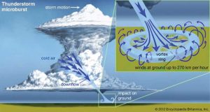
Short-term storms start as thunderstorms, but they can cause microbursts which can turn into tornadoes or hailstorms. In Alberta, on the east side of the Rocky Mountain Range, in Canada and the U.S., there are areas where downslope winds (known as Chinooks) contribute to extreme wind events. A comparable situation occurs on the maritime coasts. The U.S. (and rarely the Atlantic maritime provinces) have tropical storms, hurricanes, and/or typhoons.
Code provisions
The wind load provisions in U.S. and Canada are different, but they also have some similar provisions.
 [5]
[5]In the U.S., ASCE-7 has several chapters dealing with wind provisions. Chapter 26 has the general calculation for wind loads. The wind design load, qz, is the design wind pressure on a structure occurring over a three-second period. The wind load calculated using equation is:
- qz = 0.00256KzKztKeV2 [lb/ft2]
- p = [lb/ft2]
- Kz = velocity pressure exposure coefficient
- Kzt = topographic factor
- Ke = ground elevation factor
- V = basic wind speed, [mi/hr]
- p = qKd GCp – qiKdGCpi
- Cpi = pressure coefficient for interior element
- Cp = pressure coefficient for exterior element
- G = gust factor
- Kd = wind directionality factor
This article focuses on four of the variables:
The design velocity in the U.S. is taken over a sample for a time of three seconds, with a probability of exceedance of 0.33 percent, 0.14 percent, 0.06 percent and 0.03 percent (return period of 300, 700, 1,700, 3,000 years), at a height of 33 ft (10 m) above ground, depending on the risk category of the structure.
Over the years, the criteria for basic velocity have changed. This has been for several reasons, the improvement of the measurement of wind speeds (anemometers) and unifying the design approach for both winds in hurricanes and synoptic winds. The change from just using one return period wind to using return periods of 300, 700, 1,700, or 3,000 years, was introduced in the 2010 edition of ASCE-7.
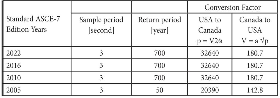
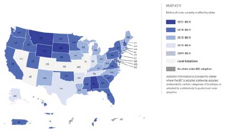


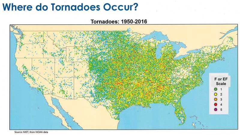

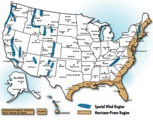


Table 1 shows the ASCE-7 edition with the basic wind speed and a conversion equation between ASCE-7 to NBC.
It is accepted by the construction and design communities that areas where the basic wind speed is greater than 125 mph (201 km/hr) 1/700-year wind, ASCE-7-22, 100 mph (160 km/hr) ASCE-7-05, the area was considered a high-wind zone requiring special detailing. Converting design wind speed for use in Canada, the same criteria is used for buildings in areas where the 50-year pressure is greater than 0.55 kPa (11.5 psf); therefore, special framing needs to be considered.
Design pressure (q): this is calculated from a design wind. The design wind in Canada is the average wind pressure taken over 60 minutes with a probability of exceedance of two percent (return period of 50 years) at a height of 10 m (33 ft) above ground in open terrain.
Exposure factor (Ce): the exposure factor accounts for the effect of the surrounding terrain. Rough and open terrain are the only two exposure categories considered.
In Canada, the NBC covers wind load in Article 4.1.7. The wind load equation is:
P = Iw q Ce Ct Cg Cp
A quick explanation of three of the variables:
Design pressure (q): this is calculated from a design wind (0.00256V2 [psf]). The design wind in Canada is the average wind pressure taken over 60 minutes, with a probability of exceedance of two percent (return period of 50 years), at a height of 33 ft (10 m) above ground in open terrain. When wind speeds over a 60-minute period are compared, there are likely wind gusts in that time which are
60 percent higher than the average wind speed.
Importance factor (Iw): accounts for whether the structure is low occupancy, regular use, or high importance. For example, the structure could be used as a post-disaster shelter or a critical structure such as a hospital—equivalent to the use of risk categories.
Gust factor (Cg): is similar to G, Cg converts the design pressure into a wind pulse of three seconds on the structure and is a function of the sample period and the size of the area considered.
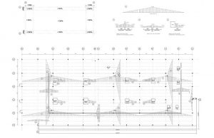
Figure 2 shows a roof section of a project in southern Alberta. The detail shows attention being paid to building science consideration. The project was constructed in an area where the design wind pressure is 0.9 kPa (18.8 psf); this pressure is the equivalent to winds from a Category 3 hurricane or an EF-2 tornado.
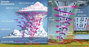
Tornadoes
Tornadoes are rotating columns of air from the ground to the base of a thunderstorm and hurricanes. They cut a narrow path of destruction about 300 ft (90 m) wide, extending out as wide as 1,700 ft (520 m). The greatest wind intensity is in the central path. Wind speeds decrease rapidly away from the vortex of the tornado, but they can still be damaging.
With large tornadoes, more damage can occur in the periphery than from the central path. Field surveys performed after tornadoes have discovered common structural failures. Some of these include:
- Bottom chord buckling of roof trusses, column base plates.
- Loss of roof decks and wall siding due to inadequate connection to the structural supports.
- Inadequate connection of walls to the foundation.
Tornadoes are classified based on the level of damage they cause. In the 1970s, the Fujita scale was developed and enhanced in the 2000s (Enhanced Fujita scale). Figure 3 provides a description of each scale, estimated wind speeds, and equivalent gust pressures.


Table 2 indicates tornado categories, wind speeds, and wind pressure.
Design for tornadoes is an evolving situation with extensive ongoing research. Tornadoes are different than other wind events as their highest wind speeds are near the ground, are very localized, and cause up to three times larger uplift forces compared to other types of wind events. With the high winds at the ground, windborne debris becomes a major concern.
In the U.S., ASCE-7 covers the design for tornadoes in Chapter 32. The provisions are the result of research done since 2011, and it reveals tornadoes mainly occur on the east side of the Rockies. The tornado risk occurring is smaller than required for a regular building. Though rare, tornadoes are more common than people may believe. On average, more than 1,200 tornadoes are reported each year and the loss of life due to tornadoes is higher than hurricanes and earthquakes combined. Tornadoes need to be considered for buildings such as hospitals (risk level 3 and 4). The first part of the chapter describes the types of buildings which do not need to be specially designed for tornado winds:
- Structures outside tornado-prone areas can rely on the wind provisions for the area (Figure 4).
- Low occupancy and regular buildings can rely
on general wind provisions for the area. - If the tornado wind speed is below 96 km/hr
(60 mph), ASCE-7 states can rely on the wind provisions for the area. - If the tornado wind speed is below a specified speed for each exposure, ASCE-7 states can rely on the wind provisions for the area.
If the building is required to be designed against tornadoes, Chapter 32 provides the basic provisions to calculate the design wind speeds. These wind speeds represent up to EF-2 tornadoes, which are 97 percent of all reported tornadoes. If there are requirements to design against the most intense tornadoes, designers are directed to “ICC 500 Storm Shelters,” or tornado performance-based design procedures are to be followed. The other wind parameters in Chapters 27, 29, and 30 can be used in the same manner as other wind loads to calculate wind loads on the structure.
In Canada, tornadoes are addressed in the “Structural Commentaries of NBC 2015.” The commentaries list three levels of risk for tornado-prone regions:
- “regions prone to significant tornadoes” are defined as regions where the estimated probability of occurrence of a significant tornado (F2–F5)
- “regions prone to tornadoes” are defined as regions where the estimated probability of occurrence of a tornado (F0–F2)
- “regions where tornadoes are possible” are defined as regions where tornadoes have been observed.
The key guidance from the commentary is:
- Details should be designed on the basis of a factored uplift wind suction of 2 kPa [41.8 psf] on the roof, a factored lateral wind pressure of 1 kPa [20.9 psf] on the windward wall, and suction 2 kPa on the leeward wall.
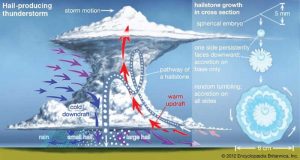
Hail
Hail is not considered a structural load. However, the occurrence of hailstorms raises one of the key specifiers’ criteria: Is the product durable?
In the U.S., Factory Mutual has identified the high-risk areas in Property Loss Prevention Data Sheets 1-34 (Figure 5).
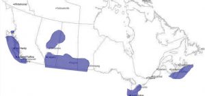
In Canada, hail occurs in the same areas as thunderstorms. Figure 6 shows the location of hail activity, with Alberta being the most active area.
Rain
Designing for rain is vastly different compared to other roof loads, and for several reasons. The structural engineer is dependent on decisions made by the mechanical engineer and architect on water drainage from the roof. Water moves and follows the geometry of the roof structure. The code provisions give the designer a method to calculate the volume of water. For example, 100 mm (4 in.) of rain over a 1,000-m2 (10,764-sf) roof gives 1,000 m3 (26,400 gal) of water. The designer is responsible to work out how the water would sit on the roof, accounting for roof slopes and how much the roof structure deflects. The rain loading is dependent on the stiffness of the roof system and its components, if the decking and supporting members are not stiff enough, the water will flow to that area and overload the structure. This is called a ponding failure.
Ponding calculations are quite complex and iterative. In the past, guidance was provided on which minimum stiffness to use and what geometry should be avoided. With additional computing capabilities now available, it is feasible to calculate ponding loads.
In the U.S., rain loads are covered in ASCE-7-22, Chapter 8. Rain loads are calculated based on obtaining an equilibrium of the rainstorm rainfall and how fast the water can drain off the roof. There is a requirement for the roofs to have two drainage systems so if the primary drains are blocked, the secondary system will drain the water. The equation for rain loads used is:
R = 5.2 (ds + dh + dp)
ds, static head—depth of water due to the elevation difference between the primary and secondary drains
dh, hydraulic head—depth of water, assuming a flow rate corresponding to
a rainfall intensity for a 15-minute duration storm of a specified return period and the drain outflow
dp—depth of water due to deflections of the roof subjected to rain and self-weight
The 2022 edition of the ASCE-7 differs from previous editions because it requires deflections due to ponding to be calculated. In past editions, the standard rules were provided of what minimum stiffness and geometry should be avoided (similar to what is in the 2015 edition of the NBC).
In Canada, there is not as much variation of rainfall as in the U.S. The NBC does not have many provisions for rain loading; they are extremely broad and general and require a lot of work to satisfy them. Section 4.1.6 states:
“The Rain load, S, due to the accumulation of rainwater on a surface whose position, shape, and deflection under load make such an accumulation possible, is that resulting from the one-day rainfall whether the surface is provided with a means of drainage. Where scuppers are provided as secondary drainage systems and where the position, shape, and deflection of the loaded surface make an accumulation of rainwater possible, the loads due to rain shall be the lesser of either the one-day rainfall or a depth of rainwater equal to 30 mm [1.18 in.] above the bottom of the scuppers.”
The NBC structural commentaries go on to advise designers:
 [6]
[6]“It is considered good practice when locating roof drains to take into account
not only the roof slope but also deflection of the roof due snow and rain. Drains should be provided with suitable devices to prevent clogging by leaves or, where appropriate, suitable overflows should be provided through parapet walls. There is potential for the primary drainage system for a roof to become blocked due to freeze-thaw conditions. Roofs should be designed accordingly.”
In his presentation of the new NBC: “Companion Loads, Wind/Snow Loading,” Dr. F.M. Bartlett discussed areas in Canada where the rain load can exceed roof snow loads. These areas are susceptible to “ponding” (Figure 7).
Snow
Snow is similar to water, as in, it moves and follows the geometry of the roof structure. High parapets, roof valleys, snow guards, changes in roof elevations, privacy screens, mechanical units, and ducting can all cause snow accumulations and increase loading. Care must be paid to the shape of a building to reduce snow accumulations. Problems occur when snow accumulates in an area not anticipated by the structural engineer.
Calculation of the weight of snow is also a challenge. When snow first falls, its density is exceptionally light, 6.4 pcf (1 kN/m3) and within 24 hours, the density doubles and can increase to 25.5 pcf (4 kN/m3) over time. If only the depth of the snow has been measured, the change in density with time makes estimating the snow load difficult.
The snow load provisions in ASCE-7 are dealt with in Chapter 7 and are calculated from the following equation:
pf = Cb Ce Ct pg
ps = Cs pf
= Cs Cb Ce Ct Is pg
Pg = Ground snow load based on a reliability analysis
Ce = Exposure factor
Cb = Ground to roof factor set at 0.70
Ct = Thermal factor
Cs = Sliding factor 1.0 ≥ Cs ≥ 0.0
In the 2022 edition of ASCE-7, the thermal factor was increased by 20 percent in value to reflect the effects of increased roof insulation or vented roof, and increased 30 percent where a complete building was used as a refrigerator.
In 2020, a major project was launched to generate ground snow loads across the country to reflect a more consistent level of safety, matching what is required by ASCE-7. Achieving a more consistent level of safety was done following a “reliability approach.” This method could only be done at this time because of the amount of computing capacity required to do this.
The work was done in the following manner:
The snow load was compared to the resistance of a steel roof:
- The steel resistance probability distribution was used based on research by the American Institute of Steel Construction (AISC).
- The snow load probability distribution was calculated based on a ground to roof conversion probability distribution.
o The ground snow load probability distribution based on annual maximum snow load records across the country.
o Snow depth to load conversion equations for different parts of the country at locations where only snow depth was measured.
Using all these distributions, Monte Carlo simulations were done. Snow loads that would cause failures were found at each site for low-occupancy buildings, normal occupancy buildings, and high importance only for an acceptable number of times.
The new snow maps have improved the prediction of ground snow loads across the U.S.; and the project results improved the prediction of snow loads across the country. The new ground snow load maps have less areas requiring special studies to establish ground snow loads, and the new maps have dealt with areas where local codes used different loads than in ASCE-7.
The differences between NBC and ASCE-7 are the ground snow load pg and the basic roof factor Cb. In Canada, snow loads are a combination of the basic roof factor and the thermal factor. The 1953 edition of the NBC first dealt with design snow loads. The roof loads were equal to the ground snow load, with reductions allowed for sloped roofs only. The load values were approximate and resulted in over-design for some roofs and under-design for others, particularly in areas subject to high-drift loads.
Between 1957 and 1968, The National Research Council of Canada (NRC) undertook a country-wide survey of snow loads on roofs. This survey provided evidence on the relationship between ground and roof loads and enabled the committees responsible for the 1960 edition of the NBC to adjust the code requirements.
In 1960, roof loads were set at 80 percent of the ground load, and they were adjusted to allow for the increase in the load caused by rainwater absorbed by the snow. At the time, NRC researchers recognized if a roof was cold and in a sheltered area, the snow load remained at 100 percent of the ground snow.
However, this possible variation (now Cb) was not documented in the structural commentaries or the NBC. By 1965, all roof loads were directly related to the snow load on the ground. The basic design load remained at 80 percent of the ground load, but a snow load of 60 percent of the ground load (Cw) was allowed for roofs exposed to the wind.
Snow accumulations were accounted by means of snow load coefficients or accumulation factors, and these were shown in the form of simple formulas and diagrams, similar to those still used in 2015.
Presently, in NBC 2022, snow load provisions are found in Article 4.1.7. The equation for snow load is:
S = Sr + Cw Cb Ca Cs Ss
Sr rain load: for the winter months, a probability
of exceedance of two percent (with a return period of 50 years)
Ss ground snow load: based on weather data and has a probability of exceedance of two percent (with a return period of 50 years)
Cb ground to roof factor: set at 0.80
Cao accumulation factor
Cw wind factor: 1.0 ≥ Cw ≥ 0.5
Cs sliding factor: 1.0 ≥ Cs ≥ 0.0
Two of the variables are affected by architected details.
Many engineers believe the value of Cb remains constant at 0.7, no matter what roofing system or amount of roof insulation is used. When this value was first considered, the researchers involved debated whether Cb should be one or less. As Dr. D.A. Taylor reported in his paper, “Roof Loads in Canada”:
“The design load coefficient for a uniformly on a well-insulated or unheated roof in a perfectly sheltered location Cb = 1.0.”
Cold roofs, as mentioned earlier, have been addressed by modifying Ct in ASCE-7-22.
For those people considering an energy retrofit or meeting the new energy requirements, an R-30 insulated roof is well-insulated and a ventilated roof is considered as unheated.
For the sliding factor Cs to be considered, the snow needs a path to slide off. If snow is prevented from sliding off due to snow guards, parapets, or another structure, the roof must take the full snow load.
Occupancy loads
Roofs not only have to resist environmental loads but also loads from human use of the roof area. Most of the occupancies are ones which architects are used to dealing with. The one loading that is different, is an allowance for doing maintenance work on the roof. Both U.S. and Canadian codes have requirements for a minimum roof live load for maintenance work on the roofing system to prevent collapse.
The minimum live load requirements for both countries are similar.
The U.S. has had minimum load provisions since 1943. The provisions, in their present form, first appeared in the Uniform Building Code (UBC) in 1949. They allow the minimum load to be reduced based on the tributary area the roof member is supporting and on the roof’s slope. The requirements are as follows:
- 20 psf (0.96 kPa ) reducing to 12 psf (0.58 kPa), depending on a combination of tributary area and roof slopes.
- Greenhouses, and farm accessory buildings
10 psf (0.48 kPa).
In 1988, a lower value for the minimum roof load was allowed if repair work is done from the ground and approved by the local authority.
Prior to 1985, there was confusion in Canada about the purpose of the minimum roof live load. The load allowance was considered by many as a minimum snow load. Since 1985, the NBC clarified the minimum roof live requirements as an area load of 20.9 psf (1.0 kPa) and a point load of 290 lb (1.3 kN).
The structural commentaries, since 1985, explain these load allowances are for use and occupancy loads, not a minimum snow load intended to provide for maintenance loadings, workers, and so forth, and the load allowances are not reduced as a function of area or roof slope.
Dead loads
With roofs, the contractor needs to know what weights are always on the roof structure and what allowances are provided for items that may or may not be there. There are many terms for describing these dead loads that might be there. This author prefers the term “collateral dead load.”
The load allowances for mechanical ductwork and architectural bulkheads are examples of collateral dead loads. The reason for identifying these is when:
- checking for uplift due to wind load on the roof structure, the structural engineer should only use the dead load
or
- checking for loads which are pushing down on the roof structure, the structural engineer should use the dead load and collateral dead load.
The locations of mechanical units, ductwork, and architectural bulkheads should be reviewed with the structural engineer. Often, these items are handled by delegated design and the structural engineer is never made aware of them. This is especially true for architectural bulkheads and ceilings.
Connection details for hanging loads have been identified as an area structural engineers should be aware of and not left to a sub-trade to do. The engineer for the sub-trade should know the type of detail that is acceptable to the structural engineer of record.
Project manual
Roof design and its systems and components involve all the design disciplines, for example, roofing Division 7, structure Divisions 3, 5, or 6, reflected ceiling plans and bulkheads gypsum board assemblies Division 9, lighting Division 26, and HVAC ductwork Division 23.
Roof design can be handled in many ways: by the owner’s design team, delegated designers, or a combination of both. The same considerations also apply if the owner’s design team (professionals of record) do all or part of the design work. The transfer of design information is the same for all these approaches.
The author’s preferred approach of interacting and sharing design information is to supply it through drawings and specifications. In the author’s case, they need to supply the loads the roof components must resist and how they should attach to the roof structure. The load information that needs to be conveyed is shown below:
- Dead load
o Constant
■ Self-weight, mechanical units
o Collateral
■ Mechanical ductwork
■ Architectural finishes (ceilings, bulkheads)
- Live loads
o Minimum live load
- Wind loads
o Load on roof membrane
o Projections off the roof (mechanical units and screens)
- Snow loads
o Basic snow load
o Snow buildup due to
■ items on the roof (mechanical units and ductwork), screens
■ roof geometry
- Rain load
o Distribution due to roof geometry and deflection of members
In Section 1603.1 of the UBC, the following information should be shown in the construction documents:
- a) sufficient detail for the dead loads to be determined
- b) all effects and loads, other than dead loads, used for the design of the structural members and exterior cladding
- c) the dimensions, location, and size of all structural members in sufficient detail to enable the design to be checked
 [7]
[7]The author puts the main portion of the design loads on the roof structural drawings and adds the required information in the general notes (Figure 8).
Mechanical ducting or gypsum assemblies are often supported off the roof structure. This can be done in two ways: typical details on the structural drawings with the specifications cross referencing the details, or sketches included in the specification section of the sub trade. Often, the latter are missed and catch the sub trades by surprise. Commonly, architectural sub trades do not look at, or are not given, the structural documents by the general contractor.
One of the greatest challenges is coordination of the roof design and getting mechanical, electrical, and architectural information supplied to the structural designer. Often, coordination is seen as how all the different trades geometrically fit together, and is not thought of as the cost implications of what is being designed by the different trades.
In the case of roof design, the impact of hanging loads have a significant impact on the structure if the clear spans of the roof structural members exceed 9 m (30 ft). The author recommends the project’s coordinating professional receive line drawings showing weights for mechanical ductwork, fire sprinkler lines, lighting, and architectural finishes. Transferring this information is best done during design development but can also be part of the submittal process during construction. The coordinating professional can identify the impact of these weights on the structure and optimize the layout of the suspended loads. In the author’s experience, there is significant structural savings if the loads are evened out across the roof structure.
Conclusion
Roof design requires coordination and cooperation of all the design disciplines to ensure no design details are overlooked. Each separate discipline impacts the other often more than designers recognize; therefore, communication is critical.
Considerations, all of which must be recorded in the project manual, include extreme weather systems such as wind gusts, tornadoes, hail, rain, snow, and both occupancy loads and dead loads on roofs.
Author’s note: I would like to thank the following people who reviewed this article, provided advice, and emendations on the details, Jan Dale PE, technical director, principal with RWDI; Keith Robinson FCSC, FCSI, RSW, LEED AP, associate, specifier with DIALOG; and Dr. Brennan Bean, associate professor, Utah State University.
 Author
- [Image]: https://www.constructionspecifier.com/wp-content/uploads/2023/04/354-002a.jpg
- [Image]: https://www.constructionspecifier.com/wp-content/uploads/2023/04/Figure_1a_Gust_Front.jpg
- [Image]: https://www.constructionspecifier.com/wp-content/uploads/2023/04/Figure_1b_Tornado.jpg
- [Image]: https://www.constructionspecifier.com/wp-content/uploads/2023/04/Figure_1c_Micro_Burst.jpg
- [Image]: https://www.constructionspecifier.com/wp-content/uploads/2023/04/Figure_1d_Hail_Storms.jpg
- [Image]: https://www.constructionspecifier.com/wp-content/uploads/2023/04/Figure_9-1.jpg
- [Image]: https://www.constructionspecifier.com/wp-content/uploads/2023/04/Figure_10.jpg
Source URL: https://www.constructionspecifier.com/essential-structural-considerations-in-roof-design/