Estimating R-values for enclosed reflective air spaces
by Katie Daniel | January 5, 2017 3:46 pm
 [1]
[1]by David W. Yarbrough, PhD, PE
Reflective insulation systems (RIS) consisting of a reflective insulation material and an adjacent enclosed reflective air space have been used as building thermal insulation in the United States for nearly a century. ( For more, see W. P. Goss and R. G. Miller’s “Literature Review of Measurement and Predictions of Reflective Building Insulation System Performance; 1900−1989,” in the American Society of Heating, Refrigerating, and Air-conditioning Engineers’ ASHRAE Transactions [vol. 95, part 2 (1989)].) Despite this longevity, there continues to be hesitation in many cases to specify and evaluate the thermal performance of these systems for use in building envelope applications.
Well-vetted R-values based on a large number of measurements have been available to practitioners for more than 40 years (This comes from the 1972 edition of the ASHRAE Handbook of Fundamentals—“Thermal Conductances and Resistances of a Plane Air Space,” Chapter 20, Tables 2a, 2b, and 2c.), and the Federal Trade Commission (FTC) Home Insulation Rule contains guidance for labeling and advertising of reflective insulation products. (The rule’s official name is 16 CFR Part 460, Labeling and Advertising of Home Insulation, § 460.5 [3b – d].) The FTC rule contains specific requirements for advertising thermal resistance values. This article’s purpose is to provide for a quick estimate of thermal performance for a specific set of conditions or a well-defined application.
What is reflective insulation?
Reflective insulations include single-sheet products that consist of low-emittance foils or films bonded to a substrate such as paper, plastic, or polyethylene bubblepack and multiple-layer insulations. In most cases, both sides of the single-sheet insulation are faced with low-emittance foil or film. When only one side has a low-emittance surface, it is important to install that facing the enclosed air space. Reflective insulations with low-emittance surfaces on both sides are often used to create two enclosed reflective air spaces in a series.
The reflective insulation products with multiple layers are installed to form two or more enclosed reflective air spaces. The specified number of layers and the spacing must be present for the expected thermal resistance to be achieved.
Enclosed reflective air spaces are labelled with RSI-values that have the same units and same meaning as other building insulations. The thermal performance of reflective assemblies varies with temperature, as is the case with all insulations. R-values for thermal insulation materials typically decrease as the temperature increases. Products are labelled at a particular temperature—for example, 24 C (75 F)—so comparisons of competing products can be made on a uniform basis.
A reflective assembly consists of two parts. The thermal resistance associated with the enclosed air space (i.e. R#-value) plus the R-value of the reflective insulation material.
Estimation of thermal performance for reflective insulation
Detailed calculations and test results of RIS performance have been published in the past (For more, see this author’s co-written paper with Andre O. Desjarlais, “Prediction of the Thermal Performance of Single and Multi-airspace Reflective Insulation Materials,” which appeared in ASTM Special Technical Publication [STP] 1116, Insulation Materials: Testing and Applications, second volume, edited by R.S. Graves and D.C. Wysocki [1991].), with sophisticated computer simulations released more recently. (See Hamed H. Saber et al’s “Numerical Modeling and Experimental Investigations of Thermal Performance of Reflective Insulations,” published in the Journal of Building Physics [36 (2)] in 2012.) In both of these cases, the papers are intended for specialists rather than general design professionals. Fortunately, ISO 6946, Building Components and Building Elements−Thermal Resistance and Thermal Transmittance: Calculation Method, approaches its estimation of thermal resistance values in a simpler manner. (See the ISO standard’s Annex B, “Thermal Resistance of Air Spaces.”)
Since thermal insulations in the United States are labeled for R-value at 24 C (75 F), the estimation procedure that follows has been set up to evaluate on RIS at this mean temperature or 534.69 Rankine—the corresponding absolute temperature. In addition, the model has been extended to include temperatures from −23 to 71 C (−10 to 160 F). The estimates are for unventilated air spaces of uniform thickness with both the length and width of the air space at least 10 times the thickness. The accuracy of an estimate is reduced when the dimensional restrictions are not satisfied. R#-value estimates include heat transfer across the enclosed air space by conduction, convection, and radiation.
Unlike many well-known building thermal insulations (e.g. expanded polystyrene [EPS] or fiberglass), the thermal resistance for a RIS depends on heat-flow direction and the thermal emittances of the surfaces perpendicular to the heat-flow direction (e1 and e2). The R#-value also depends on the distance (d), in inches, across the air space and the temperature difference, DT in °F, across the air space.
The thermal resistance of an RIS is the sum of R# and the thermal resistance of the reflective insulation material, Rmaterial, which is small in most cases.
 [2]
[2]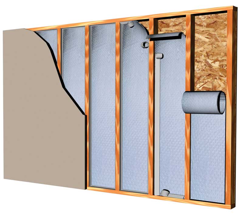 [3]
[3]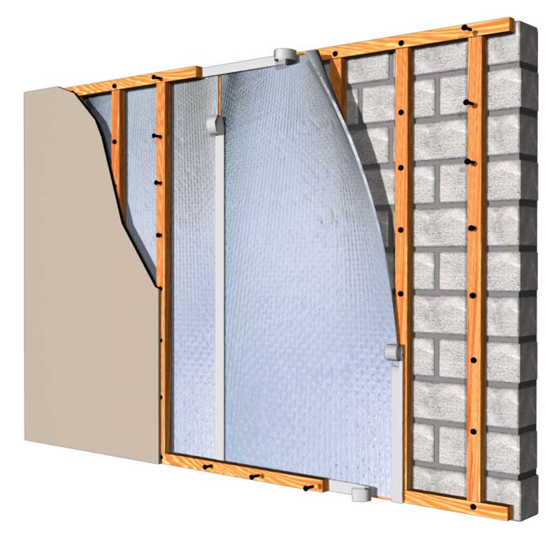 [4]
[4]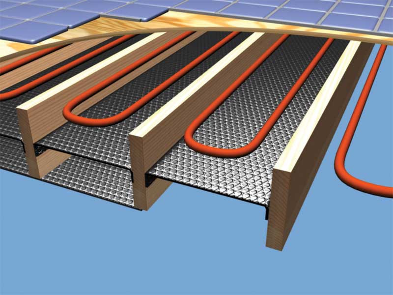 [5]
[5]


Thermal resistance calculation
The equations for estimating the thermal resistance of an enclosed rectangular air space are taken from ISO 6946, but have been converted for use with IP units. The heat-flow consists of two parts, each represented by a heat transfer coefficient (h). Heat-flow by radiation is represented by hrad, while heat-flow by conduction-convection is represented by hcc. The thermal resistance, R#, of the air space is calculated from the two heat-transfer coefficients using Equation 1:
![]()
The radiation term depends on the average temperature of the air space, T (in degrees Fahrenheit), as shown by Equation 2:
![]()
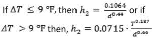
The conduction-convection term is taken to be the greater of h1 and h2, quantities that are calculated from the following equations. Equation 3 differs from ISO 6946 due to the introduction of the variation of the thermal conductivity of air with temperature:
![]()
Depending on the direction of the heat-flow, Equation 4 can differ in three ways. When there is upward heat-flow, one should use Equation 4a:
![]()
When there is horizontal heat-flow, one should use Equation 4b:
![]()
When there is downward heat-flow, one should use Equation 4c:
The R# estimate based on Equations 1 to 4 proceeds as follows:
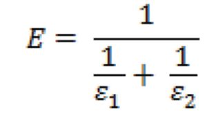
Step A: Determine the emittances of the two surfaces and calculate E.
Step B: Choose T and calculate hrad.
Step C: Choose d (i.e. distance across air space in inches) and calculate h1.
Step D: Select the heat-flow direction and calculate h2.
Step E: Identify hcc, which is the larger of the two numbers: h1, h2.
Step F: Calculate R# using Equation 1.
Step G: Thermal resistance for the RIS equals R# + Rmaterial.
A practical example
To illustrate how this works, a practical example is in order. A 1 ¼-in. air space of interest is anticipated to be at 75 F, with a temperature difference across the air space of 6 F. One side of the air space has emittance 0.9, while the second side of the air space has emittance 0.03. The heat-flow direction is downward.
- From Equation 2: E = 0.0299 and hrad = 0.0313
- From Equation 3: h1 = 0.1438
- From Equation 4c: h2 = 0.0964
- From Step E: hcc = 0.1438
- From Equation 1: R# = 5.71 sf·h·F/Btu
Selecting T and ΔT, and a quick estimate for R
The temperatures for the R# calculation depend on the materials present in the section of the building envelope containing the enclosed reflective air space, as well as the temperatures of the exterior and interior surfaces of the section. Under steady-state conditions, the T and DT can both be calculated as follows:
- Rext = the sum of R-values on the exterior side of the air space;
- Rint = the sum of R-values on the interior side of the air space; and
- R# calculated for DT = 5 °F and 75 °F—reasonable starting temperatures in many cases.
Rmaterial can be included as either exterior or interior thermal resistance, depending on its location.
Figure 1 contains a diagram showing the locations of the above thermal resistances. If the exterior surface temperature is 38 C (100 F), and the interior surface temperature is 21 C (70 F), then:
- T (exterior surface of air space) = 100 − 30·Rext/(Rext + R# + Rint); and
- T (interior side of air space) =70 + 30·Rint /(Rext + R# + Rint).
The temperature difference across the air space is the absolute value of the temperature difference, a positive number:
I T(exterior surface of air space) – T(interior side of air space) I
The average temperature for the air space is:
[T(exterior surface of air space) + T(interior side of air space)]/2.
The average temperature and the ΔT can be used to calculate a new value for the R# of the enclosed reflective air space. If a precise value for R# is the objective, then the above process can be repeated until the sequence of estimated R#-values becomes constant. This calculation can be done using a spreadsheet program such as Excel.
As mentioned, building insulations in the United States are labeled with R-values determined at 75 F. It seems reasonable, therefore, to make a reflective air space estimate at that mean temperature. Calculated R-values for the air space with DT of 5°F and a second calculation with DT equal to 10 F will provide a range of likely values for the air-space thermal resistance in many cases. Figure 2 contains estimates for R# for air spaces from 1⁄2 to 2 in., with a low-emittance surface on one side.
How good is the estimate?
The enclosed air-space R#-values in the American Society of Heating, Refrigerating, and Air-conditioning Engineers’ ASHRAE Handbook of Fundamentals include selected results obtained from a large number of hot-box tests. (See the 2014 ASHRAE Handbook of Fundamentals, “Effective Thermal Resistances of Plane Air Spaces,” Chapter 26, Table 3.) R#-values estimated using ISO 6946 compare favorably with the ASHRAE values.
A few comparisons of air-space R#-values from the two sources are shown in Figure 3.
The comparison of R#-values from two sources is quite good in the absence of convection, as should be the case for heat-flow down. The two methods for obtaining R# use different approaches for the convective contribution, and the results differ by as much as 25 percent in the case of heat-flow up, as shown in Figure 3.
The R#s calculated with the ISO method are intended to be used for quick estimates of the potential benefits of using a reflective insulation in the building envelope. The heat-flow is taken to be one-dimensional and steady-state. This estimation provides a way to obtain the reflective air-space R#-value estimates for conditions not in the ASHRAE tabulations. It is important to know these estimates do not include multidimensional effect, which, in most cases, tends to reduce the R# for the enclosed air space. Nevertheless, the ISO model provides useful information for exploring several potential advantages of adding a reflective component to the building envelope.
Final comments
This article shows the procedure for calculating the thermal resistance of a planar enclosed air space, as published in an international standard formatted to provide results with IP units. A limited comparison with hot-box results represented by R#-values published by ASHRAE shows agreement for heat-flow down and heat-flow horizontal. The small R-values provided when the heat-flow direction is up differ by as much as 0.5 or 25 percent in a few of the cases listed in Figure 3.
The R#-values in this discussion are for single air spaces enclosed and oriented as indicated by the heat-flow direction. ISO 6946 allows use of an average value for ‘d’ when an air space is tapered. The model is useful for exploring the performance for different climate regions, with thermal resistance increasing as temperature is reduced. However, these calculations are not intended to replace or satisfy any legal requirements for labeling and advertising.

 [6]
[6] [7]
[7]


David W. Yarbrough, PhD, PE, is vice-president of R&D Services Inc., an accredited, independent laboratory specializing in thermal insulations and related building materials. Yarbrough is an emeritus professor of chemical engineering at Tennessee Technological University, and a registered engineer in the states of both Tennessee and Florida. He is also a member of the Building Enclosure Technology and Environment Council (BETEC), an active member of ASTM Committee C 16 (Thermal Insulation), the International Thermal Conductivity Conference, and the American Society of Heating, Refrigerating, and Air-conditioning Engineers (ASHRAE). Yarbrough can be contacted via e-mail at dave@rdservices.com[8].
- [Image]: https://www.constructionspecifier.com/wp-content/uploads/2017/01/metalbldg_wall-C.jpg
- [Image]: http://www.constructionspecifier.com/wp-content/uploads/2017/01/reflective_Under-sub-floor-over-concrete1.jpg
- [Image]: http://www.constructionspecifier.com/wp-content/uploads/2017/01/reflective_Stud-Wall-Between-Joists2.jpg
- [Image]: http://www.constructionspecifier.com/wp-content/uploads/2017/01/Masonary-Wall1.jpg
- [Image]: http://www.constructionspecifier.com/wp-content/uploads/2017/01/Rad-Fl-Wood-Double-Layer-300-CMYK8.jpg
- [Image]: http://www.constructionspecifier.com/wp-content/uploads/2017/01/Reflective_Fig2.jpg
- [Image]: http://www.constructionspecifier.com/wp-content/uploads/2017/01/Reflective_Fig3.jpg
- dave@rdservices.com: mailto:dave@rdservices.com
Source URL: https://www.constructionspecifier.com/estimating-r-values-for-enclosed-reflective-air-spaces/