Everything Leaks: Testing roofs to ensure watertightness at the outset
by Katie Daniel | February 6, 2017 10:39 am
 [1]
[1]by Ronald J. Ray, RA, CCS, CCCA, CSI, AIA
All roofs eventually leak—it is just a matter of when and where. Nevertheless, the hope is that new roofing systems do not leak right from the start. It is critical to verify the watertightness of roofing, especially if it is to be covered with ballast or a vegetated roof assembly. This verification is a field quality-control measure beyond the scope of a roofing manufacturer’s visual inspections for issuance of a warranty. For existing buildings being considered for a reroofing program, conducting a roof survey to determine the location and extent of wet substrates is essential to making fiscally responsible decisions related to the program’s extent.
Flood-testing to detect leaks and verify the quality of newly installed assemblies has a long history in the roofing industry. ASTM D5957, Standard Guide for Flood Testing Horizontal Waterproofing Installations, is a guide for conducting flood-testing of horizontal surfaces with slopes no greater than 1/4 in. per foot (i.e. 1:48). It is commonly referenced as the standard for flood-testing roof systems. However, ASTM D5957 specifically states the standard “is not intended for use on building roofs.”
ASTM D5957 references a maximum water depth of 100 mm (4 in.). This translates to an added live load during testing of 101.34 kg/m2 (20.76 psf). Water depths and the associated live load at roof drains would be even higher. Further, the National Roofing Contractors Association (NRCA) does not recommend flood-testing of new roof systems. According to Joan P. Crowe, AIA, NRCA’s director of technical services, flood-testing is inappropriate for identifying potential leak sources. Crowe states roof systems are designed to resist the passage of water with a minimal amount of hydrostatic pressure (i.e. flowing water), while waterproofing systems are designed to prevent the passage of water under hydrostatic pressure (i.e. standing water).
For example, roof drains are not designed to be leak-free under hydrostatic pressure, so it is highly likely they would leak at this location’s flashing during a flood-test. Although flood-testing can determine the existence of a leak, it cannot precisely identify the location, even with use of soluble dyes in the water. If flood-testing is still desired by a specifier, it may need to be performed in segments when roof drains are separated by large distances. Critical sheet flashing conditions and terminations may be similarly assessed by localized water testing.
Other technologies, such as electronic leak testing, can detect leaks with far more reliability than flood-testing. Some electronic leak-testing methods include:
- electrical capacitance/impedance testing;
- infrared thermography;
- nuclear hydrogen detection;
- low-voltage electrical conductance testing; and
- high-voltage spark testing.
Electrical capacitance/impedance testing
A nondestructive procedure used to identify entrapped water within a roof system, electrical capacitance/impedance testing may not produce a significant result on new construction. This method works due to the ability of water to store or conduct electrical energy. The procedure involves placing a hand-held moisture meter on the surface of the roof, which sends an electrical current into the roof without penetrating its membrane. Wet insulation provides less resistance to the electrical current than dry insulation. Therefore, if the underlying material is wet, the electrical conductance is great and registers on the meter.
It is important to note these meters only determine whether the area is wet or dry. They do not quantify the percentage of moisture present within the roof insulation, nor do they pinpoint the location of the leak. Additionally, the roof surface must be dry in order for these meters to produce accurate results. ASTM D7954/D7954M, Standard Practice for Moisture Surveying of Roofing and Waterproofing Systems Using Non-destructive Electrical Impedance Scanners, establishes requirements for conducting electrical impedance scans of roof assemblies.
 [2]
[2]Photo © International Leak Detection
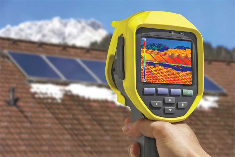
Infrared thermography
Infrared thermography (or infrared imaging) works by locating areas of increased roof temperatures caused by entrapped water within a roof system, typically within the above-deck insulation. As is the case with electrical capacitance/impedance testing, it may not produce significant results on new roof construction. Additionally, this test method is not effective with protected membrane systems after the insulation has been placed above the roof membrane, or with roof decks capable of retaining significant quantities of construction water. Examples of the latter condition include:
- lightweight structural concrete decks;
- lightweight insulating concrete decks;
- lightweight-cellular insulating concrete decks; and
- poured gypsum decks.
When used with roof systems incorporating insulation that does not absorb water, such as expanded polystyrene (XPS) or closed-cell sprayed polyurethane foam (SPF), infrared thermography has not produced adequate results. During cold weather, heat lost from the interior of a building is greater through areas of wet roof insulation, meaning the temperature of the roof surface is increased at those locations. In warm weather, solar heat is absorbed into areas of wet roof insulation and retained, creating an increase in the temperature of the roof surface at these locations. An infrared image identifies the areas of increased roof surface temperatures.
Increased surface temperatures may also be produced by several phenomena unrelated to moisture intrusion, such as:
- ponding water atop the roof membrane;
- points of heavy gravel or ballast applications; and
- under-deck heating and cooling vents.
Consequently, electric capacitance/impedance testing or nuclear backscatter testing (discussed later in this article) is typically used to verify the results of infrared thermography.
Clear weather conditions with light wind are required for infrared thermography testing. The optimal time of day for this testing is after sunset. ASTM C1153, Standard Practice for Location of Wet Insulation in Roofing Systems Using Infrared Imaging, establishes requirements for conducting both ‘ground-based’ and aerial infrared imaging of roofing systems.
Nuclear hydrogen detection
Also known as the ‘backscatter’ methodology, nuclear hydrogen detection employs a radioactive isotope to emit high-speed neutrons aimed at the roof. This method relies on the thermalization, or slowing, of fast neutrons by the hydrogen atom contained in water to locate entrapped water within a roof system. As such, it may not produce significant results on new roof construction, much like infrared imaging and electrical capacitance/impedance testing.
The measuring instrument incorporates a periodic counter that gauges the rate at which the neutron atoms are thermalized by the hydrogen atoms contained in any water present in the roof assembly. Since other hydrogen-bearing materials also thermalize neutrons, a relative base level must be established for each roof assembly prior to testing. While this system cannot determine the amount of moisture contained in a roof assembly, it can determine the difference between wet and dry insulation. American National Standards Institute/Single-Ply Roofing Industry/RCI International (ANSI/SPRI/RCI) NT-1, Detection and Location of Latent Moisture in Building Roofing Systems by Nuclear Radioisotopic Thermalization, establishes requirements for nuclear hydrogen detection related to roof assemblies.
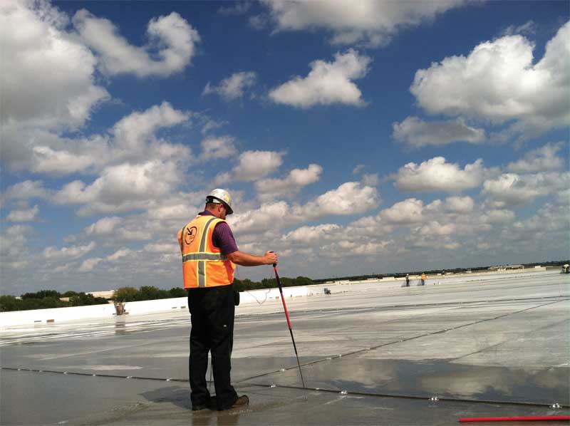
Low-voltage electrical conductance
Low-voltage electrical conductance testing specifically locates areas of discontinuity of the roof membrane rather than entrapped water within a roof assembly. The most common system is Electric Field Vector Mapping (EFVM)—a proprietary system developed by International Leak Detection in the 1990s in Germany and introduced to North America in 2001. Worldwide, this system has tested more than 18.5 million m2 (200 million sf) of membranes.
The process works by grounding a conductive roof deck, such as steel, beneath a nonconductive roof membrane, and locating places where a low-voltage electrical field goes through the roof. This is accomplished by dampening, but not flooding, the roof, and placing an uninsulated wire loop around the perimeter of the area to be tested. The wire loop is connected to a low-voltage pulsating generator that emits a one-second 40-volt charge every three seconds, creating a momentary electrical field between the wire loop and the grounded roof deck. The roof membrane acts as an insulator between the electrified wire loop
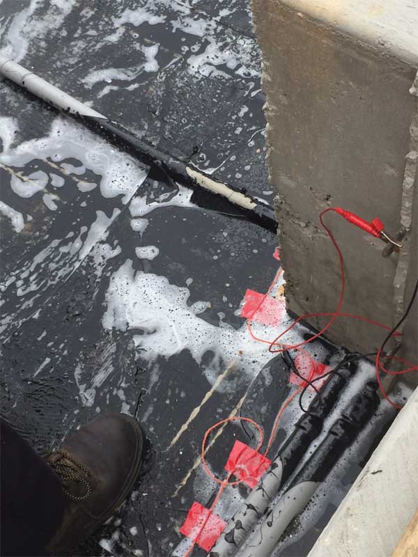
and the roof deck. Electrical charges over the moist membrane surface will be random unless there is a discontinuity or ‘leak’ in the membrane. If there is a leak, a directional current is created, which can be followed to the leak using a potentiometer connected to two probes making contact with the roof surface.
Test reports include specific numbered locations of any breach of the membrane. For nonconductive roof decks, such as wood, a conductive medium is built into the roof assembly. Common media include:
- welded stainless-steel mesh for adhered roof
systems; and - welded wire mesh for non-conductive substrates.
For ballasted and vegetated roof assemblies, testing can be performed with the overburden in place. For vegetated roof assemblies, the roofing manufacturer may require installation of a low-voltage electrical conductance testing system in order to issue a special warranty.
 [3]
[3]Photo courtesy Luna and Associates
A similar system to this proprietary methodology uses a small scanning platform of approximately 457 x 609 mm (18 x 24 in.), which incorporates a perimeter wire loop of chains that hangs from the platform, making contact with water on the roof surface, as well as a separate line of chains located in the center of the platform. Both series of chains are connected to a low-voltage power source. The platform is moved along the surface of the roof membrane to detect breaches similar to the EFVM system.
Low-voltage electrical conductance testing cannot be used for roofs with a vapor retarder, because the vapor retarder will hide roof leaks by blocking the electrical field, just as the roofing does. Additionally, this testing method will not work with an electrically conductive roof material such as black ethylene propylene diene monomer (EPDM) because it contains carbon black. Similarly, it is unsuitable for roofs with aluminized protective coatings, which are commonly employed over modified bituminous (mod-bit) membranes.
There are two advantages of low-voltage electrical conductance testing over traditional flood-testing and other types of electronic leak testing:
- It can provide leak detection throughout the life of the roofing, precisely locating leaks with pinpoint accuracy.
- It can test sloped roofs and vertical walls.
High-voltage spark testing
High-voltage spark testing is similar to low-voltage electrical conductance testing, but uses a 1000- to 30,000-volt direct current (DC), and does not require a wet membrane or wire loop. The system uses an electrically charged metal ‘broom’ connected to the power source, which is grounded to a conductive roof deck. When the metal broom passes over a discontinuity in the dry roof membrane, the electrical circuit is complete, and an audible sound is generated by the testing equipment.
High-voltage spark testing cannot be used for roofs with a vapor retarder, for the same reason described for low-voltage electrical conductance procedures. Likewise, it will not work with an electrically conductive roof material such as black EPDM or membranes using aluminized protective coatings. For ballasted and vegetated roof assemblies, testing must be performed before the overburden is in place. The roof membrane must be completely dry for this testing method to work. Due to the higher voltage used, more false positives have been reported with this testing method than with low-voltage electrical conductance testing.
The advantages of high-voltage spark testing over traditional flood-testing are its capability to provide leak detection throughout the life of the roofing, to precisely locate leaks, and to test sloped roofs and vertical walls.
Conclusion
With such advancements in electronic leak detection, the industry has access to an array of testing options far superior to flood-testing. Each option has its own advantages and disadvantages. Factors to consider when selecting a leak detection testing procedure include:
- the size of the roof;
- cost of testing;
- availability of testing within the geographical region of the building; and
- for existing roofs, the extent of possible leaks as evidenced by interior damage to the building.
Ronald J. Ray, RA, CCS, CCCA, CSI, AIA, is an architectural specification writer with ARCOM with almost 40 years of experience. Previously, he was in private practice as an independent specification consultant for architectural, structural engineering, and civil engineering firms, producing more than 420 project manuals for a wide range of project types. While employed at different architectural firms, Ray was a project manager, project architect, and designer, specializing in the design of churches, schools, and professional sports facilities. During his 32 years of membership in CSI, he has served on the board for two different chapters, chaired committees, and written bylaws for both chapters. Ray can be reached at rray@arcomnet.com[4].
- [Image]: https://www.constructionspecifier.com/wp-content/uploads/2017/02/bigstock-Recording-Solar-Panels-With-Th-105092978.jpg
- [Image]: https://www.constructionspecifier.com/wp-content/uploads/2017/02/3-Low-Voltage-Electrical-Conductance-EFVM.jpg
- [Image]: https://www.constructionspecifier.com/wp-content/uploads/2017/02/5-Low-Voltage-Electrical-Conductance-EFVM.jpg
- rray@arcomnet.com: mailto:rray@arcomnet.com
Source URL: https://www.constructionspecifier.com/everything-leaks-testing-roofs-to-ensure-watertightness-at-the-outset/