Evolution of masonry cavity wall designs
by Katie Daniel | April 4, 2018 3:05 pm
 [1]
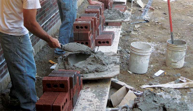
[1]by Paul Potts
Masonry cavity drainage construction became the norm when architects and masons came to the realization a simple empty space separating two wythes of masonry with a layer of insulation could provide as much comfort as several feet of solid barrier masonry.
This article explores three types of masonry cavity wall designs:
- simple cavity drainage walls;
- air-vented cavity drainage walls; and
- rainscreen pressure-equalized cavity walls.
Each of the three wall masonry cavity types has similar features, including:
- an exterior brick wythe acting as a rainscreen;
- a supporting wythe of 200-mm (8-in.) concrete masonry units (CMUs); and
- a separating cavity partly filled with insulation.
While the cavity space may be between 50 and 114 mm (2 and 4 ½ in.) (for more information, refer to the Brick Industry Association’s [BIA’s] Technical Note 21, “Brick Masonry Cavity Walls[2]”), the minimum required clear space between the outer face of the insulation and the back of the brick is 25 mm (1 in.) in order to permit clear, unobstructed drainage. (Consult BIA’s Technical Note 7, “Water Penetration Resistance–Design and Detailing.[3]”) It should be noted cavity open spaces less than 50 mm are difficult to keep clear of mortar bridging. (Read the National Research Council Canada’s [NRC’s] publication, “Evolution of Wall Design for Controlling Rain Penetration.[4]”)
Simple cavity drainage walls
The simplest cavity drainage wall consists of:
- an exterior brick wythe, which takes the brunt of the rain;
- a cavity with weep holes at the bottom providing drainage for rainwater penetrating the brick;
- insulation; and
- a supporting backup CMU.
Wind pressure is shared by the brick veneer and inner wythe of the CMU, which are connected by brick ties.
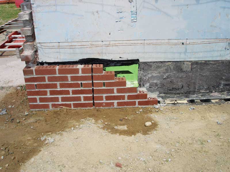
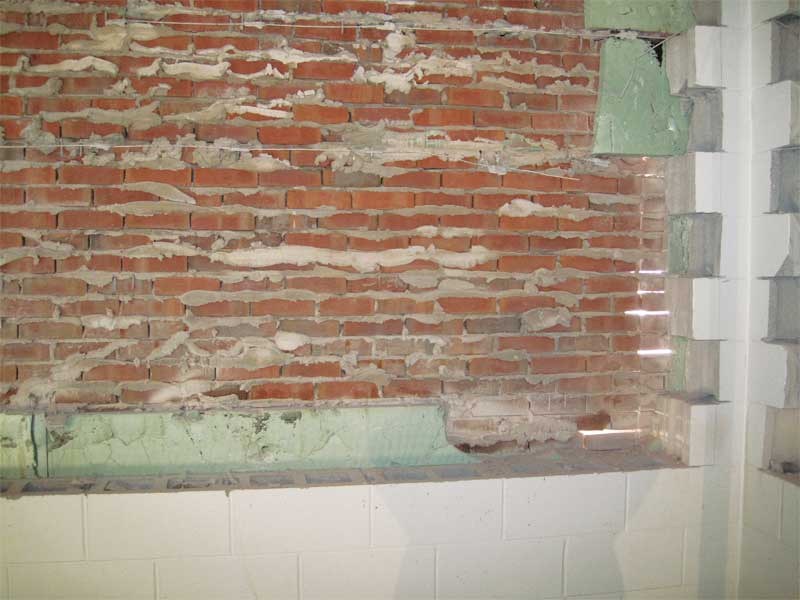
Water collecting in the bottom of the cavity is drained to the exterior through a flashing and weep hole system. Weep holes, which are small round holes filled with wicking at the bottom of the cavity, can be replaced with open head weep joints that do a better job of draining the cavity. Much water remains behind because mortar droppings plug the weep openings and water accumulates on wall ties and other bridging. A drainage media at the bottom of the cavity helps break up the mortar droppings before they reach the weep openings, but the drainage media itself can become plugged.
 [5]
[5]Air-vented cavity drainage walls
Mortar joints in the brick masonry are the weak points. Rainwater driven by wind pressure penetrates the brick veneer by diffusion, capillary action, and convection. However, convection (water hitching a ride on air movement) through hairline cracks in leaky mortar joints transfers 200 times as much moisture into the cavity and the building as the other two sources combined. (Get additional details at masonryadvisorycouncil.org/wp-content/uploads/2016/06/Using-Air-Barriers-in-Masonry-Walls.pdf[6].) Moisture streams into the building through openings in the CMU, which could be prevented with an effective air barrier.
Open head joint air vents 609 mm (24 in.) on center (o.c.)—one at the bottom of the wall (combined with a weep joint) and another directly above, at the top
of the wall—induce air circulation in the cavity by differential air pressure. Air venting cycles through the cavity, carrying moisture away by convection. Air enters at the lower opening where pressure is higher and exits at the top where pressure is lower.
A partially compartmentalized air-vented cavity wall with battens at the corners of the building, as well as an air barrier and moisture retarder on the cavity face of the CMU, begins to emulate the effectiveness of its more complicated cousin, the pressure-equalized rainscreen cavity wall, but at a sharply lower cost.
 [7]
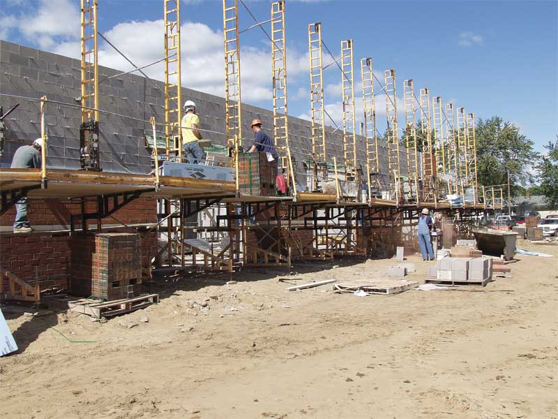
[7]Rainscreen pressure-equalized cavity walls
In his 1962 paper, “Curtain Walls,” Øivind Birkeland of the Norwegian Building Research Institute wrote:
The only practical solution to the problem of rain penetration is to design the exterior rainproof finishing so open that no super-pressure can be created over the joints or seams of the finishing. This effect is achieved by providing an air space behind the exterior finishing, but with connection to the outside air. The surges of air pressure created by the gusts of wind will then be equalized on both sides of the finishing.
(Read the full report here[8].)
In 1963, following up on Birkeland’s assertions, the Canadian National Research Council’s (NRC’s) Division of Building Research issued Canadian Building Digest (CBD) 40, “Rain Penetration and Its Control.” Thus began the scientific engineering and design of pressure-equalized rainscreen walls.
The premise of pressure-equalized cavity design is: most of the moisture getting into the cavity is carried there by air movement (convection) propelled by wind pressure entering the cavity through leaky mortar joints on the windward side. The pressure in the windward cavity escapes into the building through breaches in the CMU backup and escapes around corners of the building to other areas of the cavity on the leeward sides. This depressurization allows a continuous movement of moisture-laden air to circulate throughout the cavity and into the building.
The pressure-equalized system works by allowing wind gusts to enter the cavity through openings at the bottom of the brick veneer. However, it is stopped from flowing into the building and leeward walls by an effective air barrier and moisture retarder, as well as battens compartmentalizing the cavity. This system causes the cavity to pressurize, equalizing with the wind pressure outside. Therefore, moisture-laden air can no longer enter the cavity. (Visit www.gobrick.com/Portals/25/docs/Technical%20Notes/TN27.pdf[9] to read BIA’s Technical Note 27, “Brick Masonry Rainscreen Walls.”) Wind pressure is dynamic, rising and falling in gusts. This helps to keep the cavity dry, because each time the wind pressure drops, the pressurized cavity breathes out, carrying moisture with it.
The pressure-equalizing technique requires:
- open joints to allow wind pressure to enter the cavity;
- a continuous air barrier between the cavity and the building interior; and
- battens to compartmentalize the cavity.
The combined area of the open joints in the bottom of the cavity wall must be calculated based on the size of the cavity. Therefore, it is important to keep the cavity as narrow as practical.
While designing an airtight backup wall to prevent air pressure from escaping into the building, calculating the area of air openings at the bottom of the wall, and sizing the compartments in the cavity is challenging enough for architects, it is also difficult to prepare construction documents anticipating every breach between the cavity and the building. It is more likely many unanticipated breaches in the inner wall would have to be covered by a contingency budget and change orders.
 [10]
[10]Air barriers and moisture retarders
Better workmanship could improve the watertightness of the mortar joints, but an air barrier and moisture retarder are needed to prevent moisture from entering the building.
Many designers recognize the need for a moisture retarder on the exterior face of the CMU, but tend to overlook the importance of an air barrier. According to a study by the National Institute of Science and Technology (NIST), the energy savings from a well-constructed air barrier can be as much as 33 percent of the annual energy cost. (Visit www.nist.gov/news-events/news/2005/10/simulations-predict-savings-more-airtight-buildings[11] for more information.)
Cavity wall designs should place an air barrier and moisture retarder on the cavity face of the CMU to avoid creating a gap where moisture could condense between the two materials. Products with both air barrier and moisture retarder properties eliminate the need to install two separate assemblies.
Moisture retarders should be on the warm side of the insulation to prevent moist, warm interior air from condensing in the insulation in winter climates and on the exterior side of the insulation in hot, humid climates. This is a conundrum for the architect to resolve in regions experiencing some
of both extremes.
Insulation in cavity walls
Three types of insulation are used for masonry
cavity walls:
- extruded polystyrene (XPS) moisture-resistant rigid board insulation;
- foil-faced polyisocyanurate (polyiso) rigid foam insulation; and
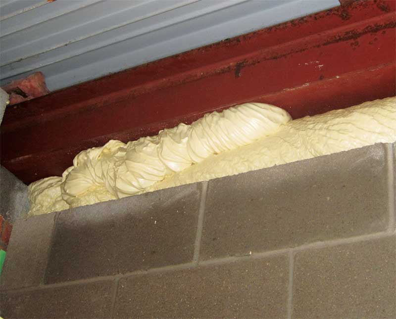
- closed-cell sprayed polyurethane foam (SPF) insulation.
XPS insulation offers moisture resistance and long-term durability. It is lightweight, easy to handle, and can be cut into smaller pieces. XPS comes in 400-mm (16-in.) widths, 1.2-m (4-ft) lengths that can be pressure-fit between the wall ties. A misgiving about XPS is its rigid configuration makes it difficult for enclosing irregular shapes and openings for a complete air barrier.
Dual foil-faced polyisocyanurate rigid foam insulation in 400-mm (16-in.) widths and up to 3-m (10-ft) lengths is recommended for cavity wall insulation. It has a higher R-factor than XPS at the standard test temperature of 24 C (75 F). However, studies have shown the R-value of polyiso steadily declines as the temperature goes below 15 C (59 F). (Consult Building Science Corporation’s Info-502, “Temperature Dependence of R-values in Polyisocyanurate Roof Insulation.[12]”)
Closed-cell SPF insulation has sound/air barrier and moisture retarder properties. The adaptability of SPF to foam into irregular openings and cover irregular shapes makes it a potential complement to the rigid products in the perfection of air barriers. This adaptability helps simplify the design of cavity drainage walls, air-vented cavity walls, and especially pressure-equalized cavity walls.
Cautions about SPF have been published in ASTM STP1549, Dimensional Stability Considerations in Spray Polyurethane Foam Air Barriers:
One of the most significant problems experienced recently in the use of SPF for air barriers is short- and long-term shrinkage variations in the foam system, particularly when applied to the exterior of the building. Such shrinkage can result in damage to flashings, closures, and terminations in exterior veneer systems. This document explores the potential causes of excessive shrinkage in SPF systems, the physical changes that can cause the problem, and best practice measures to minimize the potential for significant problems during installation.
In a paper published in 2013, the Brick Institute of America (BIA) reported concerns raised in the ASTM paper had not been addressed by sprayfoam manufacturers. Regardless of these concerns, SPF has an important place in the design of pressure-equalized rainscreen walls and air-vented cavity walls to make airtight building envelopes.
 [13]
[13]Workmanship
Every effort should be made to weatherproof brick veneer joints by improving the workmanship. There are two characteristics of the bond between brick and mortar—extent and strength.
The extent of bond, the more important of the two for weatherproofing joints, refers to how completely the mortar is spread in intimate contact with the
brick across the entire surface of the joint—a result of the mason’s skill and mortar’s workability. An experienced mason can feel if the mortar is sticking to the brick properly and adjust, if necessary, by rewetting brick or retempering mortar that has gotten too dry on the board.
A few more workmanship practices can improve the efficiency of cavity wall construction. Masons can reduce mortar dropping by sloping the mortar in the bed joint away from the cavity and buttering the head joint more carefully. Additionally, one must not slush mortar on the joints. Mortar joints on the cavity side of the CMU must be cut flush to allow rigid insulation to fit tight to the wall and prevent creating a hollow space where moisture can collect.
Issues for the designer
- The roof flashing over the top of the masonry wall must come down far enough on the face of the brick wythe to prevent rain from blowing up under the flashing and entering the cavity from the top. Rain will be blown up the wall under the flashing at a rate of 22 mm (1 in.) for each 16 km/h (10 mph) of wind speed.
- Cavities for pressure-equalized rainscreen walls must be kept as narrow as practical to facilitate the increase of air pressure in the cavity.
- Due to their hidden condition and potential for allowing a continuous flow of moisture-laden air into the building, openings between the top of a masonry wall and a hip roof condition must be filled with a permanent product, not stuffed with batt insulation.
- The brick wythe should rest on a foundation ledge below the floor level in order to prevent rainwater from being driven under the weep vent flashing and into the building. The same attention must be given to brick ledges in multistory construction.
Conclusion
The design and construction of a successful pressure-equalized rainscreen cavity wall is a challenge for the designer and inspector. This type of wall is also expensive to build. It is difficult to imagine construction drawings for a large commercial building anticipating all the potential breaches in the air barrier wall requiring special treatment to make an airtight barrier. The alternative would be a large contingency budget and a considerable number of change orders to deal with unforeseen conditions—something most designers and owners prefer to avoid.
This makes a well-designed vented cavity wall with an air barrier, moisture retarder, and a partial compartmentalized cavity a good alternative to a pressure-equalized cavity wall. The air-vented wall anticipates some moisture will enter the cavity and provides air circulation to dry it out.
Paul Potts is a technical writer, owner’s representative, and construction administrator. He has worked in the construction industry as an independent contractor and administrator for architects, engineers, and owners in Michigan. Potts can be contacted at paulpotts1@comcast.net[14].
- [Image]: https://www.constructionspecifier.com/wp-content/uploads/2018/04/1-Masons-Buttering.jpg
- Brick Masonry Cavity Walls: http://www.gobrick.com/Portals/25/docs/Technical%20Notes/TN21.pdf
- Water Penetration Resistance–Design and Detailing.: http://www.gobrick.com/portals/25/docs/technical%20notes/tn7.pdf
- Evolution of Wall Design for Controlling Rain Penetration.: http://www.nrc-cnrc.gc.ca/ctu-sc/ctu_sc_n9
- [Image]: https://www.constructionspecifier.com/wp-content/uploads/2018/04/2-weep-joints.jpg
- masonryadvisorycouncil.org/wp-content/uploads/2016/06/Using-Air-Barriers-in-Masonry-Walls.pdf: http://masonryadvisorycouncil.org/wp-content/uploads/2016/06/Using-Air-Barriers-in-Masonry-Walls.pdf
- [Image]: https://www.constructionspecifier.com/wp-content/uploads/2018/04/3-Rising-Scaffold.jpg
- here: http://brage.bibsys.no/xmlui/bitstream/handle/11250/2408111/Saertrykk117.pdf?sequence=1
- www.gobrick.com/Portals/25/docs/Technical%20Notes/TN27.pdf: http://www.gobrick.com/Portals/25/docs/Technical%20Notes/TN27.pdf
- [Image]: https://www.constructionspecifier.com/wp-content/uploads/2018/04/4-SPF-Insulation.jpg
- www.nist.gov/news-events/news/2005/10/simulations-predict-savings-more-airtight-buildings: http://www.nist.gov/news-events/news/2005/10/simulations-predict-savings-more-airtight-buildings
- Temperature Dependence of R-values in Polyisocyanurate Roof Insulation.: http://buildingscience.com/documents/information-sheets/info-502-temperature-dependent-r-value
- [Image]: https://www.constructionspecifier.com/wp-content/uploads/2018/04/5-Excess-Mortar.jpg
- paulpotts1@comcast.net: mailto:paulpotts1@comcast.net
Source URL: https://www.constructionspecifier.com/evolution-of-masonry-cavity-wall-designs/