Extruded polystyrene in protected membrane roof assemblies
by brittney_cutler | January 27, 2022 8:00 pm
 [1]
[1]In roofing assemblies for low-slope concrete roof decks, protected membrane roofs set the bar for cost-savings, labor-efficiency, and roof life span among other advantages. These advantages may appear counterintuitive: Common sense suggests the roof’s waterproofing covering needs to be on top, protecting all the other components of the assembly from the elements of nature, including the insulation. Nonetheless, the primary moisture barrier (or waterproof roof covering) itself tends to be the weak link when exposed to environmental stresses.
When the waterproof membrane is on top of insulation, the relative expansion and contraction of the roofing assembly due to thermal cycling can be detrimental to roof longevity. Conversely, on a ‘typical’ roof, hailstorms and maintenance foot traffic both bear potential of mechanically damaging an exposed roof membrane. Additionally, the waterproofing membrane on top of the insulation can act as a vapor barrier, allowing moisture to accumulate in and around the insulation beneath the membrane, causing a whole different set of problems.
For these and many other reasons, protected membrane roofing assemblies are beneficial and desirable in modern building and construction.
 [2]
[2]Changing paradigms in roofing
The use of protected membrane roof assemblies (PMRAs) received a boost with the parallel developments of robust membranes that could support the weight of the assembly and water-resistant insulating materials. Fiberglass- or polyester-reinforced modified bituminous roofing membranes provide a seamless monolithic roof covering membrane that could last for many decades—especially when shielded from UV radiation and punctures. Coupled with boards of extruded polystyrene (XPS) insulation placed on top of such extremely durable, continuous, moisture-resistant roof coverings, the use of PMRAs gained acceptance among architects and construction specifiers.
According to a comprehensive account by Watts[3], in the early years of PMRAs, these roofs consisted of XPS insulation embedded in the flood coat of an asphalt built-up roof. This technology was quite successful in extending the service life of built-up roofs. By the 1980s, much was known about the performance of these ‘upside-down roofs’ which had the waterproofing membrane underneath the insulation rather than on top. Roofing materials were also changing. Modified bituminous roofing membranes were gaining in popularity. A new generation of these commercial roofing systems began entering the market under the PMRA designation. (see Figure 1)
A versatile roof
 [4]
[4]Aside from the obvious advantage of extended service life compared to traditional low-slope commercial roofing systems, PMRAs offer several other attractive features and benefits. Once the waterproofing membrane is installed, the building is sealed, and the building interior work can begin immediately. Concurrently, complex assemblies can be constructed on top of the building, tailoring the roof to the needs of the locality, as in the following examples (see Figure 2):
If the environ around the building behaves as an urban heat island, then the roof assembly can be designed to mitigate this effect. The urban heat island effect can be countered with a vegetative or landscaped roof or with the use of reflective materials for the top layers of the roof assembly;
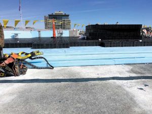
If water runoff from sudden downpours is a problem in the building environ then a blue roof design may be desirable. The roof itself can serve as a water detention container;
 [5]
[5]A hybrid ‘green & blue’ stormwater management system allows some water to be captured by the roof and reused as non-potable ‘grey water’ for various suitable building needs, such as flushing toilets and watering lawns. This roof design reduces the demand from the water utility by repurposing water usage in areas where water conservation is important;
Occupiable roofs are also flourishing. There are countless designs for occupiable roofs with innovation abounding. Architects are only limited by their imagination. Occupiable roofs can be used for anything from rooftop dining and social gatherings to urban farming and recreational activities. High compressive strength extruded polystyrene (XPS) insulation competently supports occupiable roofs without compromising the performance of the roof assembly;
Photovoltaic (PV) panel assemblies are readily installed on top of buildings with PMRAs. The structural components above the waterproofing membrane provide a foundation for the framework that supports the solar assembly. Penetrations of the membrane and deck can be avoided using a PMRA as the firm foundation for PV panels.
PMRAs require competent engineering to accommodate the dead and live loads on the insulation. Specifiers must also consider the buoyancy of the insulation. (XPS insulation floats quite well in water.) Nonetheless, a properly designed PMRA is a versatile roof, offering many advantages to a building owner. PMRA designs are continually being improved upon and are growing in popularity.
 [6]
[6]Using XPS insulation in PMRAs
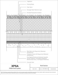
The simplest PMRA consists of: (1) a waterproofing membrane installed on a concrete deck or other appropriate substrate; (2) XPS insulation boards placed on top of the membrane; and (3) ballast loaded on top of the XPS insulation boards (see Figure 3).
The insulation in roof assemblies provides long-term energy efficiency and resists applied structural loading. A properly specified roof assembly withstands compressive forces from dead loads and potential live loads and complies with fire classification requirements for the roof covering and the roof assembly. In addition to these requirements, insulation in PMRAs must deliver thermal performance while being exposed to Mother Nature’s moisture. A variety of insulation materials could meet performance requirements for commercial roof assemblies, but XPS is uniquely qualified for PMRA applications because it delivers long-term thermal performance even when exposed to moisture.
Ballast may consist of concrete pavers, aggregate, or even growth media in the case of a vegetative roof. Depending on the ballast, a fabric or other components may be installed above insulation and below the ballast. Specially designed layers also may be needed between the insulation and the membrane to provide separation for drainage as well as specialized protection (such as root barriers on vegetative roofs). Joints between XPS do not need to be sealed and in some cases it may be better to not seal the joints to permit water vapor to escape the roof assembly. For PMRAs roofs, XPS is not the air barrier or the water resistive barrier, rather, it acts as the thermal barrier for the roof. Regardless, the XPS should be installed in accordance with the manufacturers instructions for the application.
 [7]
[7]A key part of a PMRA design is the specification of the insulation boards. Since the earliest use of protected membranes, dating back to the 1950s, it was recognized extruded polystyrene (XPS) is uniquely well-suited for this application. The roof covering, of course, is protected by the insulation boards and not vice versa; hence, the insulation boards are exposed to moisture. They become wet and do not dry out quickly because the water typically collects just above the roof covering before it is drained. Evaporation of moisture from the roof is slowed because the insulation layer blocks sunlight and lowers the temperature of the roof covering.
In the half-century since PMRAs were first developed, the superior moisture resistance of XPS has been well documented. XPS is a hydrophobic material, which means water will bead up and run off its surface. XPS resists moisture absorption much better than expanded polystyrene (EPS) foams. A recent white paper from the Extruded Polystyrene Association (XPSA) analyzes the effects of long-term exposure to moisture on the thermal performance of polystyrene insulation. The continuous microstructure of XPS resists the absorption of water into the insulation. Consequently, XPS is more resistant to moisture penetration and related freeze-thaw damage compared to other insulation materials.
An important property of interest for the roof’s design would be determination of the total R-value required for the climate zone, which would then dictate the thickness of XPS. For more on climate zones, see American Society of Heating, Refrigerating and Air-Conditioning Engineers
(ASHRAE) 90.15 and the International Energy Conservation Code (IECC)6 (see Table 1) XPS provides a high R-value per inch (R-5) along with excellent moisture resistance.
Table 1. Descriptions of Climate Zones
| International Energy Conservation Code (IECC) | |
| Subarctic | Zone 8 |
| Very Cold | Zone 7 |
| Cold | Zone 5 and 6 |
| Mixed-Humid | 4A and 3A counties above warm-humid line |
| Mixed-Dry | Zone 4B |
| Hot-Humid | 2A and 3A counties below warm-humid line |
| Hot-Dry | Zone 3B |
| Very Hot – Humid | Zone 1A |
| Marine | All counties with a ‘C’ moisture regime |
The choice of XPS ‘type’ for PMRA systems is dictated by the compressive strength that is required for the PMRA application to withstand the loads expected on the roof. These dead- and live-loads may include auxiliary equipment and vegetation as well as foot traffic and vehicular traffic. XPS is classified by ASTM C5787 CAN/ULC-S701.18 into types by compressive strength. PMRA system designers would specify XPS type(s) with compressive strengths high enough to withstand the expected loads.
 [8]
[8]The properties of XPS insulations can be varied by the manufacturing process. By varying the cell wall thicknesses between internal cells, the density and strength of the extruded polystyrene foam can be varied over quite a large range. It is interesting that for many types of extruded polystyrene insulation the moisture absorption and R-value per inch are not affected much by the ASTM type. For example, types IV, V, VI, and VII all have the same R-value per inch and the same low moisture absorption value. Yet their densities and strength vary quite a lot.
As classified in ASTM C578 and measured by ASTM C303,12 the minimum densities of XPS types are as follows, in kg/m3 (pcf):
∞ Type IV – 23 (1.45);
∞ Type VI – 29 (1.80);
∞ Type VII – 35 (2.20); and
∞ Type V – 48 (3.00).
As classified in ASTM C578 and measured by ASTM D1621,13 the minimum compressive strengths of XPS types are as follows, in kPa (psi):
∞Type IV – 173 (25.0);
∞ Type VI – 276 (40.0);
∞ Type VII – 414 (60.0); and
∞ Type V – 690 (100.0).
As a rule, higher density correlates with higher strength in XPS insulation board. Types VII and V are suitable for applications that may have high point loads, e.g. applications with raised pavers or PV arrays. Type V is capable of withstanding high loads such as what may be experienced with vehicle parking on the building’s rooftop.
XPS types IV, VI, VII, or V each would be suitable for a typical ballasted PMRA. More ballast or ballast securement may be required for high wind zones and, as a result, higher compressive strength. The International Building Code (IBC) requires ballast designs be in accordance with ASNI/SPRI RP-4.11
 [9]
[9]A roof assembly’s fire classification is a very important factor. The discussion of roof assembly fire classification is beyond the scope of this article. Specifiers are referred to ASTM E10812 or UL79013 for more about fire classification.
The overall thermal resistance of the PMRA is improved with effective drainage. Ponded water between the insulation and the membrane for long time periods could contribute to moisture absorption, which even for XPS would require R-value adjustments. For this reason and others, drainage systems are essential in most designs of PMRAs even when using XPS insulation. A PMRA typically allows for drainage between the roof covering and the XPS insulation board. A drainage gap can be accomplished with a perforated or dimpled mat made of polyethylene, rubber, or a composite material; or the XPS itself could contain channels, slots, or kerfs to aid in drainage.
There are many considerations in the design of PMRA: structural performance, wind uplift resistance, means of egress for occupiable roofs, and other factors. Fortunately, much knowledge and experience has accumulated in recent years and more and more contractors and building materials suppliers are knowledgeable of standards and best practices.
Published guidance has been developed about PMRA and is still evolving. The interested architect or designer is encouraged to contact one or more of the XPS manufacturers for recommendations on designing a PMRA that will provide maximum durability and performance.
 [10]
[10]Thermal resistance and structural integrity
Specifiers of the components of PMRAs must balance form and function with a high degree of knowledge of PMRA components.
Below the insulation, the roof covering installed to the deck and a suitable drainage system regulates the water retention;
The insulation itself is thick enough to provide the desired amount of thermal resistance; and
Above the insulation, the ballast holds down the XPS, which must be strong enough to withstand the weight of the ballast as well as variable loads such as rainfall and human or vehicular traffic.
XPS floats on water. If there are several inches of water on the roof because of a sudden downpour, then hydrostatics requires the weight of the volume of displaced water be countered with at least the same weight in ballast. Hydrostatics tells how much ballast is necessary to keep the XPS from floating.
Ballast is used to provide uplift resistance for roof assemblies that are not adhered or mechanically attached to the roof deck. However, buoyancy is not the only factor in determining the ballast requirement. The PMRA must meet standards relating to wind uplift resistance. The height of the parapet wall surrounding the PMRA has a striking effect on wind uplift. For a detailed discussion of ballast design requirements, refer to ASNI/SPRI RP-4.11
PMRA application examples
The following examples demonstrate XPS insulation solutions for various projects where performance requirements for thermal resistance and structural integrity are solved with XPS insulation. These application examples focus on the insulation layer for PMRAs.
The application examples provide general guidance for specifying various types of PMRAs. However, the details may vary from project to project and for different roof sections on the same building. It is recommended specifiers work closely with the suppliers of the XPS insulation as well as other component suppliers.
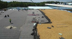
Example 1: PMRA with solar-reflective aggregate
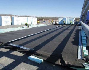
The first application example is for a ballasted PMRA assembly on top of a concrete deck with a high solar reflectivity top layer of aggregate ballast. This PMRA is for a federal building in Winchester, Virginia, which has a warm humid climate (ASHRAE 90.1 Zone 4A). The roof area is 19,264 m2 (207,360 sf) (see Figure 3).
An R-value of 5.28 K·m2/W, or R-30 (30 F·sf·h/Btu) was obtained using 152 mm (6 in.) of type VI XPS. The compressive strength of 276 kPa (40 psi) was adequate for the relatively light load on this PMRA thanks to adequate drainage. The bottom layer of the XPS insulation board itself contained drainage channels facilitating water removal through a drainage system.
 [11]
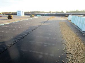
[11]A fabric material on top of the 152 mm of XPS separates the XPS from the aggregate and helps to prevent displacement of the insulation (see Figures 4 and 5). The only thing holding down the XPS insulation is the aggregate ballast. Hence, installation occurs in stages with the insulation being covered with fabric and aggregate soon after it is laid down on the waterproof roof covering.
The insulation and the reflective ballast greatly reduce the heat load on this building. This is an environmentally friendly solution because the PMRA not only extends the service life of the underlying membrane by protecting it from UV radiation and high temperatures, but also saves on cooling energy costs for this building which is in a warm humid climate.
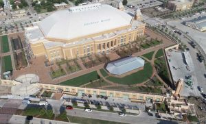
Example 2: Large multifunctional plaza deck PMRA
Another example of a PMRA roof is the Dickies Arena Plaza Deck in Fort Worth, Texas. The building is in Northern Texas which has a humid subtropical climate with mild winters and hot summers (ASHRAE 90.1 Zone 3A).
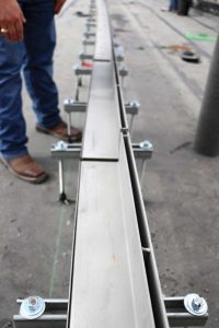
The Plaza Deck is constructed atop a concrete slab with an area of 13,006 m2 (140,000 sf). The concrete roof deck is covered with a hot-mopped waterproofing membrane. There are 261 drains at the roof deck layer, directly beneath the XPS insulation.
The Plaza Deck supports the weight of pavers, which serve as ballast and walking surfaces; concrete topping slabs (i.e. split slabs), foot traffic and furnishings; and, in some areas, vegetative roof assemblies (VRAs). Various XPS types support the differing dead and live load requirements. Type V XPS is used at locations that require the highest compressive strengths. Type V provides a minimum compressive strength of 690 kPa (100 psi).
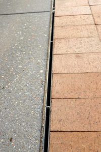
Atop the sloped structural deck, the insulation is reverse tapered to provide a flat surface; about 0.3 m (1 ft) of flat insulation follows; and finally, a third course of tapered insulation, sloping to the linear drains at the top of the aesthetic surface, completes the insulation thickness (see Figure 6). Using insulation to control heights instead of other fills such as concrete reduces the weight across the entire roof.
The layers above the insulation support the various aesthetic and functional requirements of the Plaza Deck. There are layers of filter fabric, a sand bed, pavers, and planters filled with trees. The Plaza Deck is open to visitors who can enjoy cool evenings outdoors during events at the arena. Meanwhile, when there is a downpour, the deck is engineered to efficiently drain the rainwater from this precisely engineered PMRA.
The Dickies Arena serves as an excellent example of a mixed-use PMRA application that allows for foot traffic and VRAs on a flat occupiable roof with good drainage.
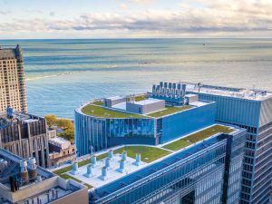
Example 3: PMRA garden roofs and water retention and detention features (blue roof)
The final example is a blue roof design in an urban area where water retention is essential (see Figure 7). Designed by Perkins + Will, the Northwestern University blue roof project involves phased construction: The 14-story base building was constructed first, and a 20-story tower addition is planned for construction five to 10 years into the future. Site conditions required a more creative approach to stormwater management than conventional, below-grade options.
The City of Chicago Department of Stormwater Management required the project account for the total building mass and footprint and a substantial detention requirement of 283 m3 10,000 cf) of stormwater. Retention volumes are different than detention volumes. Retention occurs within garden roof growing media where the water is retained until used by the plants or evaporated. Detention occurs in a blue roof where water is detained for a specific period until fully released to enter the storm sewers. This prevents flooding the sewer system. The City of Chicago Stormwater code required this stormwater volume be released through the flow control drains within 48 hours.
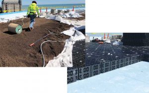
The primary stormwater detention requirement was met by creating two blue roof assemblies on the entire Level 13 and 14 roof structures. These blue roof areas were created using structural voiding units which were subsequently overlaid with garden roofs and paver assemblies for retention capacity and to provide proper ballasting. A conventional garden roof assembly was used on Level 2. The combination of the garden roofs on all levels reduced the overall detention requirement required by the City of Chicago.
To detain the blue roof water volume, roof drains were modified with a special insert that passively regulates stormwater drainage. The blue roof volume spaces were created using a structural plastic voiding component that is 95 percent open (see Figure 8). To optimize the blue roof storage, the roofs on this building were constructed with flat, zero-slope roof decks. These decks were waterproofed with a hot, fluid-applied, rubberized asphalt membrane and insulated with 178 mm (7 in.) of type VI extruded polystyrene insulation. The ability of XPS insulation to resist the wet conditions in a blue roof and green roof make it the perfect choice for thermal insulation.
Versatile solutions
As can be seen from the examples above, depending on the needs of the building environ, PMRAs can be engineered to drain water quickly, as in the case of the Dickies Arena; or retain water and gradually release it, as in the case of the Northwestern University blue roof. A PMRA can also be designed with a conventional drainage system at the roof covering level, as in the case of the aggregate topped federal building.
Another seldomly recognized benefit of PMRAs is reduced landfill. The average lifespan of a PMRA is 25 to 50 years, and the XPS insulation from such roofs can be and often is reused when the building is recovered at the end of the roof life cycle. Roof replacements send billions of cubic yards of to landfills annually. Over the lifespan of the building, PMRA roofs are better for the building owner and better for the environment.
PMRAs provide a platform for a variety of commercial and urban residential roof assemblies, including reflective and photovoltaic roofs for energy efficiency, extended roof life cycles, and vegetative roof assemblies for healthy cities. PMRAs support solutions to stormwater detention, mitigating flooding in urban areas, and contributing to water conservation. Finally, they also allow valuable outdoor areas to be repurposed as occupiable spaces.
 John Woestman is director of codes and standards to the Extruded Polystyrene Foam Association (XPSA). He has more than 30 years experience in the construction and building products industry with various responsibilities in construction, manufacturing, human resources, marketing, and codes, standards, and regulations. He has a diploma in building trades, a degree in mechanical engineering, and an MBA.
- [Image]: https://www.constructionspecifier.com/wp-content/uploads/2022/01/IMG_6473.jpg
- [Image]: https://www.constructionspecifier.com/wp-content/uploads/2022/01/XPSA-PRMA-FA-01.jpg
- Watts: http://iibec.org/wp-content/uploads/2016/03/2000-05-watts.pdf.
- [Image]: https://www.constructionspecifier.com/wp-content/uploads/2022/01/XPSA-CSI-Dickies-Arena-O-C-Fig-2.jpg
- [Image]: https://www.constructionspecifier.com/wp-content/uploads/2022/01/XPSA-CSI-Kingspan-Fig3.jpg
- [Image]: https://www.constructionspecifier.com/wp-content/uploads/2022/01/XPSA-CSI-Kingspan-Fig4.jpg
- [Image]: https://www.constructionspecifier.com/wp-content/uploads/2022/01/XPSA-CSI-Kingspan-Fig5.jpg
- [Image]: https://www.constructionspecifier.com/wp-content/uploads/2022/01/XPSA-PC-Dickies-Drains-Fig-6a.jpg
- [Image]: https://www.constructionspecifier.com/wp-content/uploads/2022/01/XPSA-PC-Dickies-Drains-Fig-6b.jpg
- [Image]: https://www.constructionspecifier.com/wp-content/uploads/2022/01/XPSA-American-Hydrotech-Beauty-Shot-Fig-7.jpg
- [Image]: https://www.constructionspecifier.com/wp-content/uploads/2022/01/Blue-roof-with-garden-roof.jpg
Source URL: https://www.constructionspecifier.com/extruded-polystyrene-in-protected-membrane-roof-assemblies/