All about the support


 FAILURES
Deborah Slaton, David S. Patterson, AIA, and Timothy Penich, AIA
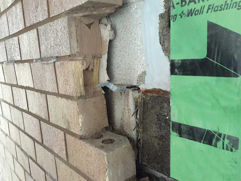
Displaced, cracked, and out-of-plane brick units were observed at the brick façade of a parking garage in a Midwestern city. The façade of the garage consisted of brick masonry veneer installed over a concrete masonry unit (CMU) backup wall. Openings made during an investigation revealed light-gauge, corrugated brick ties connected the brick veneer to the CMU back-up wall and concrete structure of the garage.
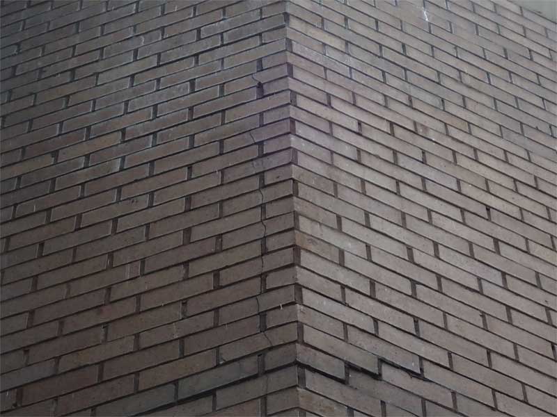
The ties, more commonly used in low-rise residential wood-framed construction, were bent in some locations (rendering them incapable to transfer loads) and were inadequately engaged in the mortar joints between brick units. The investigation also determined the CMU back-up was unreinforced, and there were no vertical expansion joints in the brick veneer at corners of the building—conditions which resulted in insufficient lateral restraint and accommodation for in-plane movement of the brick veneer, leading to the displacement and cracking of brick units on the façade.
Brick ties must connect the masonry veneer to the backup wall and transfer lateral loads (due to wind pressures) to the backup wall. They also need to accommodate in-plane differential movements of the cladding relative to the backup wall, be sufficiently stiff to transfer lateral loads with minimal deformations, have a minimum amount of mechanical play (but still accommodate vertical movement), be corrosion resistant, and be easily installed to reduce installation errors and damage to ties. The backup wall also must be structurally sufficient to resist loads imposed on it by the veneer. Brick Industry Association (BIA) Tech Note 44B, Wall Ties for Brick Masonry, provides guidance for selection of wall tie systems and their installation (building code requirements and specifications for masonry structures are provided in the Masonry Society [TMS] 402/602, Building Code Requirements and Specification for Masonry Structures).
To address the inadequacy of the existing ties, new 10 mm (0.39 in.) stainless steel helical anchors were installed through the mortar joints in the brick veneer at 406.4 mm (16 in.) on center, both vertically and horizontally. Matching mortar was applied over each helical anchor to prevent water from entering the hole and to make the repair less visible. Prior to implementation of repairs, to properly anchor the brick veneer to the backup wall, grout and steel reinforcement were installed within the cores of the CMU walls ensuring the backup masonry could adequately resist imposed loads from the veneer. Vertical expansion joints were incorporated into the brick veneer at changes in plane.
In addition to installation of the helical anchors, areas of displaced brick were rebuilt using the existing brick, which was carefully removed and salvaged for this purpose. Cracked brick units were replaced with new matching brick. Finally, mortar joints exhibiting cracking or bond separations were repointed, and new sealant was installed at expansion joints. To verify the effectiveness of the repairs, on-site testing was performed to confirm the capacity of the new helical anchors.
Sign up for our weekly newsletter
Architectural materials and methods delivered right to your inbox
- CSI News and Notes: CSI Foundation’s construction camp; CSI spring exam; and more
- CSI News and Notes: CSI’s credentials; CSI conference theme; and more
- To be specific – CSI supports young AECO professionals
- CSI News and Notes: CSI’s foundation scholarships, national conference, and Crosswalk
- CSI News and Notes: AI’s impact; CSI 2024 conference, and more
Popular Articles
-
1
-
2
-
3
-
4
-
5
Read the Latest Issue