

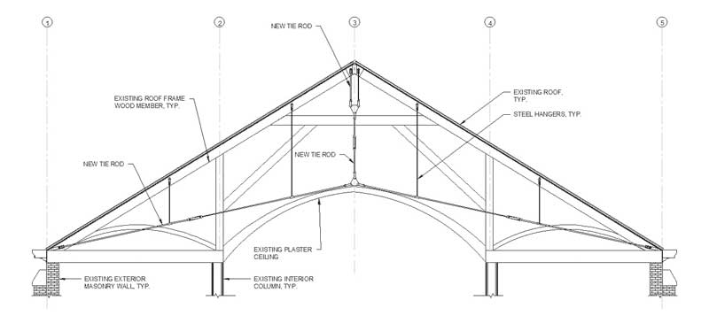
Many historic nineteenth century churches in the United States have a wood framed roof truss structure and mass masonry exterior walls. The configurations of these roof trusses can vary, but commonly include top chord members align with the roof slope and scissor type tension members rather than a horizontal tie (bottom chord) to allow for the cathedral ceilings that rise above the truss supports at the exterior wall. They may also include a horizontal tie member above the peak of the ceiling as well as diagonal knee brace type members.
Certain roof truss configurations can exert an outward horizontal force on the masonry bearing walls if there is inadequate lateral restraint at the support of the roof trusses. The exterior masonry walls may lean outward if they were not designed to resist an outward lateral force at the truss support. Exterior masonry walls that were originally intended to resist lateral loads at the roof framing supports typically include integral masonry buttresses at the truss support locations.
Since many of these historic structures were designed using empirical methods and not engineering mechanics, many times there are both deficiencies in the truss configuration and the masonry buttresses to resist the outward movement.
A common repair is to supplement the historic wood trusses with steel tension rods to eliminate the outward horizontal force at the base of the truss. Tension rod repairs are unique to each truss configuration. The repaired truss configuration, consisting of existing wood members and new steel tie rods, should be structurally analyzed, and designed for the governing load cases. Tie rods are typically designed to restrain the outward movement at the truss supports. However, a supplemental tie rod system must also be designed to prevent sagging of the tie rods over long spans.
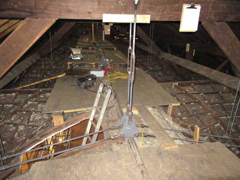
Supplemental steel rods are typically installed in a loose condition and tensioned to resist the self-weight of the roof with turnbuckles or nuts at the tie rod end support. Often, strain gauges are used to confirm the design tensile force in the rods is achieved. The steel tension rod to wood connection would typically consist of a custom steel shoe to transfer the tension force from the steel rod into a bearing force at the end of the roof truss top chord compression members. Due to the historic nature of these types of structures, it is common to find slight differences in the geometry of each truss; therefore, field verification prior to fabrication and installation of the repair is imperative.
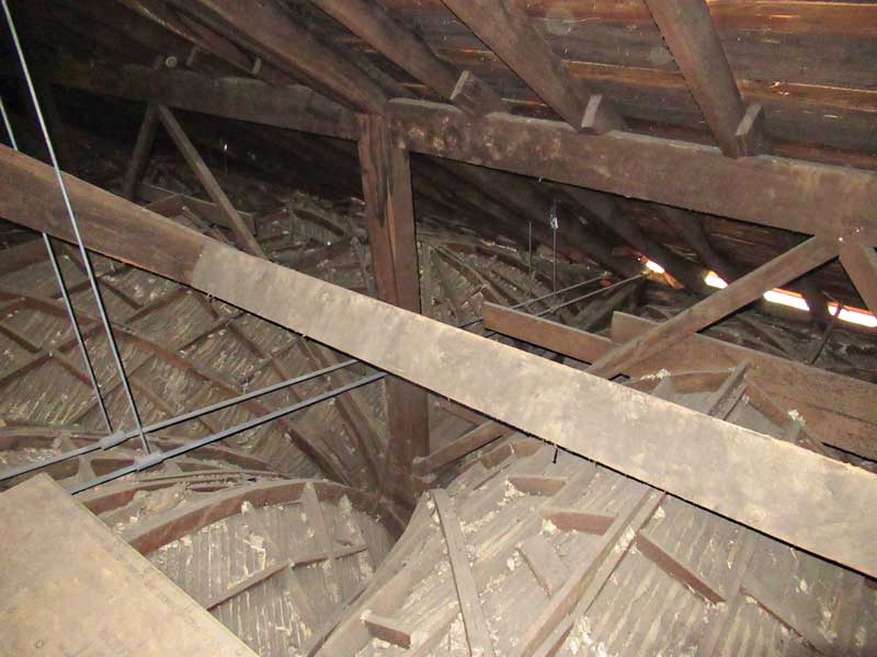
In structures with vaulted ceilings, horizontal steel tension rods spanning between the roof truss supports must extend through the roof surface and be visible in the interior space. In this example, the congregation of a historic church constructed in the mid-1800s did not want tension rods to show in the interior space. Therefore, the design team detailed a sloping scissor type tie rod system that could be located above the existing vaulted plaster ceiling and concealed in the attic space.

Kenneth Itle, AIA, is an architect and associate principal with Wiss, Janney, Elstner Associates (WJE) in Northbrook, Illinois, specializing in historic preservation. He can be reached at kitle@wje.com.

Heba Elsayed is a structural engineer and associate with WJE in Atlanta, Georgia. She can be reached at helsayed@wje.com.
The opinions expressed in Failures are based on the authors’ experiences and do not necessarily reflect that of The Construction Specifier or CSI.

