

Advances in mapping airflow
Once installed, it is clear HVLS fans deliver massive amounts of airflow throughout large spaces and, intuitively, people understand big fans produce more airflow than small fans. However, until recently, the exact amount of airflow (and its pathway) was somewhat elusive prior to installation.
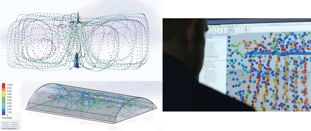
To help potential users visualize the benefits of installing an HVLS fan in their space, software based on computational fluid dynamics (CFD) can precisely track the pattern and speed of airflow in any given space, displaying the outcome in 3D video. Beyond educating building owners, such programs help remove the guesswork of fan specifications, showing the design team which sizes to use, where to place them, and at what height to hang them.
In one type of program, a building’s measurements (i.e. height, width, length), as well as its internal obstructions (i.e. racking, dividers, equipment), are entered. Fans can then be virtually placed in the space. Utilizing this information, simulations are run to visually map the airflow as it travels from the fan, throughout the space, and around obstructions.
Before such technology, the process of simulating airflow was performed on a single high-powered computer and was often lengthy and repetitive. Airflow simulation requests would come in and be added to a queue, where the lead time might grow to two weeks. Then engineers would use commercial 3D modeling software to recreate buildings (and obstructions) and place the fans. The engineers would then set up and run the flow simulation on the CFD package of the software. When the simulation was completed (usually the next day), the engineers would load the results and produce still images, animations, and a report. The development of a web application that would somehow submit data to a local server or a cloud server, model the data, render the images and animations, and return the results to the web application for easy access in less than two hours was a necessary step for the industry.
Generally, flow simulation can be broken down into three parts:
- Create the geometry and initial conditions.
- Run the simulation.
- Process the data into a usable form.
These steps needed to be automated, first locally and then integrated with a cloud server and web interface. For one program, the initial modeling package did not allow for automation, so its developers found an open-source CFD platform that could be programmed to run through all these steps. The platform was very raw and required a great deal of knowledge of both fluid dynamics and programming languages. While this was a difficulty, it also proved to be a great benefit because the program could be adjusted to automatically simulate large fans in large buildings.
Recently, the ability to input an obstruction was added to this program. Users can simulate how racking, equipment, and internal structures influence the airflow from the fan. A report was also added to summarize the data. Among other things, the report shows the average air speed in the occupied area (i.e. up to 2 m [6 ft] per minute). It also calculates the perceived temperature difference based on the average air speed and the comfort calculations found in American Society of Heating, Refrigerating, and Air-conditioning Engineers (ASHRAE) 55, Thermal Environmental Conditions for Human Occupancy. The program also has the ability to simulate the fans at variable speeds and in reverse. HVLS fans are not always run at 100 percent (at top speed, the air movement may be too fast or cool, so users adjust the systems to lower speeds), so this allows users to see the flow from their fans at lower speeds.
Automated airflow simulations bring the industry from manually building out simulations on a local computer to putting the tools in the hands of their distributors to easily do it on their own. A process that previously took two days to two weeks now only takes 30 minutes to two hours (depending on the complexity of the model). This acceleration and increased efficiency gets results to potential users faster to see how well the fans will work in their space.

