Fanning innovation in the HVLS industry
by Katie Daniel | September 15, 2017 2:31 pm
 [1]
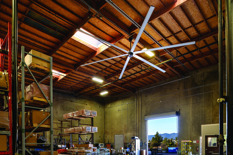
[1]by Jonathan Hollist
In 1998, dairy farmers were looking for a way to cool their cows and reduce heat stress. Air-conditioning was too expensive and it was impossible to run the ductwork in the barns. Small barn fans helped, but did not cover a wide enough area, consumed excessive and costly energy, and required ongoing maintenance. Engineers based at a fan manufacturer created a huge unit with blades spanning 7.3 m (24 ft) instead of the typical 1.5 m (5 ft). To offer a gentle breeze, the fan speed was a fraction of that of small fans. Thus, high-volume, low-speed (HVLS) fans were born.
Contrary to popular belief, not all ‘large fans’—defined in U.S. Department of Energy (DOE) testing as those larger than 2.1 m (7 ft) in diameter—are true HVLS systems. A fan must meet certain criteria to be labeled as such. The volume of air passing through the fan in one single revolution must be no less than 14 m3 (500 cf), and the speed at the tip of the blades must not be greater than 97 km/h (60 mph).
The first big industrial ceiling fans employed 10 blades. However, after extensive aerodynamic testing, designs have been re-engineered, with models using anywhere between eight and two wing-shaped blades to result in the most efficient air movement using less energy and motor torque, and reduced wear and tear on the fan.
Benefits of HVLS fans
An HVLS fan is a ceiling-mounted fan, with size being the most notable difference between it and a traditional unit. While typical high-speed fans are usually between 0.9 and 1.2 m (3 and 4 ft) in diameter, HVLS fans are 2 to 7.3 m (6 to 24 ft). The difference in size is not an accident, as these larger blades move much larger amounts of air. This is beneficial in industrial and commercial settings, since more people inhabit these buildings. Conversely, smaller high-speed fans work twice as hard, expelling larger amounts of energy to cover only a fraction of the square footage, due to the smaller blades.
The benefits of big industrial ceiling fans go beyond the massive amounts of gentle, comforting air. The lower speeds required by smaller motors allow for an incredibly efficient cooling effect at a lower cost. When paired with heating units and air-conditioners, the fans cut down energy consumption by allowing businesses to turn the heating and cooling systems down or off.
 [2]
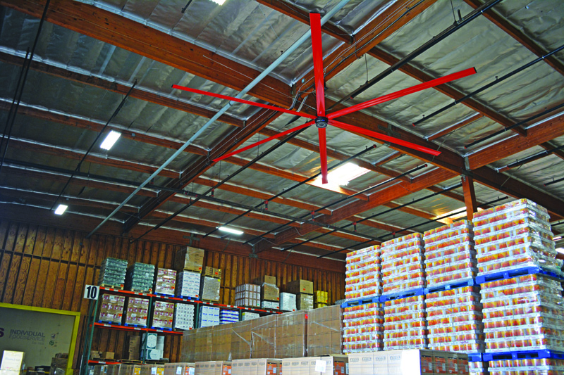
[2]HVLS fans provide environmentally sound solutions for warehouses and other commercial buildings. They enable equipment and inventory to be stored in a more hospitable environment (increasing product longevity), while helping to protect and sustain the natural environment. Many businesses are looking toward green practices, not only to better the environment and their communities, but also because the government now provides rewards and incentives for these intelligent practices. When Leadership in Energy and Environmental Design (LEED) certification is required by a local code or government agency, HVLS fans have helped projects achieve certification within the Indoor Environment Quality (EQ) and Energy and Atmosphere (EA) categories for, respectively, their ventilation capabilities and energy efficiency while maximizing HVAC effectiveness.
On a practical level, HVLS fans are more comfortable to have in a room due to the low amount of noise emitted. (The company with whom this author works has performed tests where the sound sensor is 1.5 m [5 ft] above the ground and 6.1 m [20 ft] from the center of the fan, which is 6.1 m high. The decibel ratings for these tests comes in between 50 and 60 dBa—about the same noise level as normal speech.) Smaller fans that move faster work overtime to cool a room for long periods, creating more noise. Not only does the motor on a smaller fan have to work harder to create the high speed, but the fan blades also spin faster, creating more of an uncomfortable, chilly environment.
 [3]
[3]Advances in mapping airflow
Once installed, it is clear HVLS fans deliver massive amounts of airflow throughout large spaces and, intuitively, people understand big fans produce more airflow than small fans. However, until recently, the exact amount of airflow (and its pathway) was somewhat elusive prior to installation.
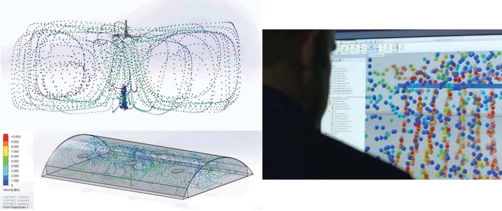
To help potential users visualize the benefits of installing an HVLS fan in their space, software based on computational fluid dynamics (CFD) can precisely track the pattern and speed of airflow in any given space, displaying the outcome in 3D video. Beyond educating building owners, such programs help remove the guesswork of fan specifications, showing the design team which sizes to use, where to place them, and at what height to hang them.
In one type of program, a building’s measurements (i.e. height, width, length), as well as its internal obstructions (i.e. racking, dividers, equipment), are entered. Fans can then be virtually placed in the space. Utilizing this information, simulations are run to visually map the airflow as it travels from the fan, throughout the space, and around obstructions.
Before such technology, the process of simulating airflow was performed on a single high-powered computer and was often lengthy and repetitive. Airflow simulation requests would come in and be added to a queue, where the lead time might grow to two weeks. Then engineers would use commercial 3D modeling software to recreate buildings (and obstructions) and place the fans. The engineers would then set up and run the flow simulation on the CFD package of the software. When the simulation was completed (usually the next day), the engineers would load the results and produce still images, animations, and a report. The development of a web application that would somehow submit data to a local server or a cloud server, model the data, render the images and animations, and return the results to the web application for easy access in less than two hours was a necessary step for the industry.
Generally, flow simulation can be broken down into three parts:
- Create the geometry and initial conditions.
- Run the simulation.
- Process the data into a usable form.
These steps needed to be automated, first locally and then integrated with a cloud server and web interface. For one program, the initial modeling package did not allow for automation, so its developers found an open-source CFD platform that could be programmed to run through all these steps. The platform was very raw and required a great deal of knowledge of both fluid dynamics and programming languages. While this was a difficulty, it also proved to be a great benefit because the program could be adjusted to automatically simulate large fans in large buildings.
Recently, the ability to input an obstruction was added to this program. Users can simulate how racking, equipment, and internal structures influence the airflow from the fan. A report was also added to summarize the data. Among other things, the report shows the average air speed in the occupied area (i.e. up to 2 m [6 ft] per minute). It also calculates the perceived temperature difference based on the average air speed and the comfort calculations found in American Society of Heating, Refrigerating, and Air-conditioning Engineers (ASHRAE) 55, Thermal Environmental Conditions for Human Occupancy. The program also has the ability to simulate the fans at variable speeds and in reverse. HVLS fans are not always run at 100 percent (at top speed, the air movement may be too fast or cool, so users adjust the systems to lower speeds), so this allows users to see the flow from their fans at lower speeds.
Automated airflow simulations bring the industry from manually building out simulations on a local computer to putting the tools in the hands of their distributors to easily do it on their own. A process that previously took two days to two weeks now only takes 30 minutes to two hours (depending on the complexity of the model). This acceleration and increased efficiency gets results to potential users faster to see how well the fans will work in their space.
 [4]
[4]Introducing advanced automation
Automation is the future of technology, so it was only a matter of time until it was introduced to the HVLS fan category. New systems featuring integrative technology for automatic fan control eliminate the need to constantly monitor and adjust fan speed and direction in response to temperature fluctuations. These assemblies identify and dictate optimal operating speed and direction for each fan based on the facility’s temperature and humidity, allowing the user to set up controls to manage when the fans run.
Advanced climate control systems are available that measure temperature and humidity at two points, calculates the heat index, and identifies the best operating speed and direction for each fan. The user selects a desired temperature range, and as the indoor temperature rises above the specified range, the fans automatically run in the forward direction at the best speed to create an appropriate cooling effect. When the indoor temperature drops below the selected temperature range, the fans automatically reverse to redistribute the heated air overhead, effectively eliminating hot and cold spots without generating a discernable breeze.
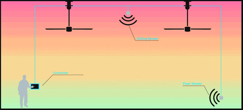
The following is an example of control features available to optimize HVLS fans. Through just one controller, users can manage up to 30 fans, with the versatility to divide these fans into four zones. With zoning, the user can customize fan operation parameters for specific areas like welding or the office. There are two sensors per zone—one at the ceiling and the other at the floor—gathering humidity and temperature data. They are independent, external sensors, so the controller can be mounted in a different room than the fans and sensors. The software then takes the temperature and humidity measurements from the sensors and calculates the heat index to understand what the temperature feels like due to humidity, rather than just the air temperature.
 [5]
[5]For such control systems, each fan model and diameter with its corresponding airflow production is programmed into the software. The system uses an advanced algorithm to determine the speed and direction based on the type of fan, the blade size, and the distance between the closest wall or fan, delivering the desired effective temperature.
When the fans are coupled with air-conditioning, the cooling effect delivered by the fans reduces the load on the air-conditioner, decreasing utility spend. In the winter, mixing the heated air will eliminate hot and cold spots, leading to savings on heating costs. Automation enables the fans to be fully optimized, maximizes energy efficiency, and provides continuous occupant comfort.
Conclusion
Since the invention of the HVLS fan in 1998, fan companies remain committed to the continual innovation and design of large, cost-effective commercial ceiling fans. Today, a wide range of HVLS fans are offered for various industries and applications, including:
- barn, agricultural, and horse and livestock fans;
- commercial ceiling fans;
- industrial warehouse and manufacturing fans;
- military fans;
- aviation fans;
- auto service fans;
- retail space fans; and
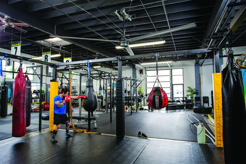
- fitness center cooling fans.
Architects and engineers are specifying new installations combining the incredible efficiency with the industrial design features of HVLS fans. It may have started in a dairy barn in Southern California, but the multi-million-dollar HVLS revolution has spread to every corner of the globe.
| AMCA STANDARDS FOR TESTING FAN PERFORMANCE |
| Testing the performance of fans, particularly those with large diameters, requires a uniform technique—Air Movement and Control Association International (AMCA) 230-15, Laboratory Methods of Testing Air Circulating Fans for Rating and Certification. To understand why the current edition of this standard is so important, it is useful to review the 1999 iteration.
Per AMCA 230-99, the fan is hung on a load cell that converts the force created by the fan into a measurable electrical signal. Placing the fan an adequate distance from the floor, ceiling, walls, and any other obstructions is critical so they do not interfere with the fan’s airflow. With the fan running at full speed, the following are tested:
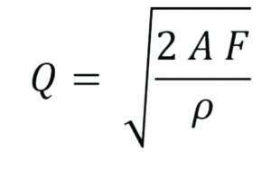
The density of the air is calculated from the temperature, humidity, and air pressure, with the information plugged into AMCA’s 230-99 equation for calculating the airflow rate (CFM) which is:
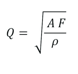
Where: Q: airflow rate; Unfortunately the ‘2’ in the above equation should not be there—it was included based on an incorrect assumption of how air flows through the fan. Calculating the airflow rate with this equation generated inflated numbers. For a few years, AMCA completely removed the cfm calculation and measuring only thrust. In 2012, AMCA reintroduced it, this time using the correct formula in its 230-12 standard:
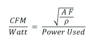
AMCA 230-12 not only corrected the formula, but also introduced an efficiency metric to explain how the fans use electrical energy. This is calculated by taking the existing cfm formula and dividing it by the power used:
Unfortunately, AMCA 230-12 is limited to fans less than 1.8 m (6 ft) In 2015, AMCA expanded the scope of its standard to include fans up to 7.3 m (24 ft) in diameter. Additionally, the U.S. Department of Energy (DOE) adopted AMCA 230-15, which means all upcoming power usage and efficiency requirements will be based on this standard. |
Jonathan Hollist is a research and development engineer at MacroAir. He has a master’s degree in mechanical engineering from Utah State University, specializing in computational fluid dynamics (CFD). Among other duties at MacroAir, Hollist is the CFD specialist and is the developer of the simulation portion of the AirViz Online Tool. He can be reached via e-mail by writing
to jhollist@macroairfans.com[6].
- [Image]: https://www.constructionspecifier.com/wp-content/uploads/2017/09/Industrial_Warehouse_Facility_MacroAir_AVD-780_3.jpg
- [Image]: https://www.constructionspecifier.com/wp-content/uploads/2017/09/Industrial_Warehouse_IFS_Bell_CA_MacroAir_AVD780_24ft_8.jpg
- [Image]: https://www.constructionspecifier.com/wp-content/uploads/2017/09/edit1-2.jpg
- [Image]: https://www.constructionspecifier.com/wp-content/uploads/2017/09/Fitness_5Elements-MMA_Costa-Mesa-CA_AVD-370_4.jpg
- [Image]: https://www.constructionspecifier.com/wp-content/uploads/2017/09/AirEffect_2.jpg
- jhollist@macroairfans.com: mailto:jhollist@macroairfans.com
Source URL: https://www.constructionspecifier.com/fanning-innovation-hvls-industry/