Fiber-cement panel siding nail head pull-through resistance
by brittney_cutler | December 29, 2021 1:19 pm
 [1]
[1]By Jacob W. Arnold, PE, Colin P. Rueb, PE, SE, and Kurt R. Hoigard, PE, SECB, F.ASTM
Since the early 20th century, fibrous cement sheets have been available for numerous construction applications. For many years, fibers in these cement sheets were primarily composed of asbestos. When the U.S. federal government passed its first legislation limiting the exposure of asbestos in the 1970s, manufacturers were forced to develop alternatives[2] to asbestos-based fibers. By the late 1970s and early 1980s, production of asbestos-containing sheet products was discontinued by many manufacturers and replaced with fiber-cement products, where asbestos was replaced primarily by cellulose (i.e. wood), glass, or synthetic fibers.
In modern construction, fiber-cement products are frequently used in exterior cladding applications, as they provide a cost-effective solution for achieving the desired aesthetic for a project. In general, fiber-cement siding is relatively thin and lightweight, and manufacturers often describe their products as having excellent durability and weather-resistance.
In general, fiber-cement panels can be classified as composite panels comprised of sand and Portland cement, reinforced with cellulose fibers and other additives, which vary depending on manufacturer specifications. To manufacture fiber-cement panel products, components are processed and combined with water and mixed into a fiber-cement slurry. The water is then drained from the slurry using cylindrical sieves, creating a thin fiber-cement film. Residual water is removed from the film using a vacuum process, forming thin fiber-cement sheets that are then stacked and fused together into a single panel using a high-pressure roller. The panels are pressed smooth or incised with a specific pattern. The act of pressing the layers together tends to increase the stiffness and moisture resistance of the material. After the pressing operations, panels are oven-cured or autoclaved—a high-temperature, pressurized curing method. Panels are once again dried, cut to size, and finished with a factory-applied coating[3].
Common amongst the various manufacturers’ installation literature for fiber-cement panel siding products is the inclusion of requirements regarding the fastener head condition. In general, a fastener can be installed in one of three conditions:
• Proud, where the underside of the fastener head is seated on the face of the surface of the fiber-cement panel;
• Flush, where the top surface of the fastener head and the surrounding surface of the fiber-cement panel are even with each other; and
• Recessed, where the top surface of the fastener head is embedded below the surrounding surface of the fiber-cement panel.
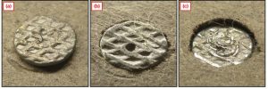 [4]
[4]Figure 2 presents representative photographs of these three fastener head conditions. The fasteners in these photographs are nails.
Review of the various manufacturers’ product literature appears to indicate a “proud” fastener head condition is typically required. Language such as, “[the] head must be snug, not countersunk or overdriven,” or, “do not overdrive the nail,” appears in various installation instructions and technical bulletins.
Although manufacturers offer generally consistent fastener installation requirements, these requirements are frequently not followed in the field. The authors have observed numerous cases of fiber-cement panel installations with nail head conditions other than the required “proud” condition, including cases where the pull-through resistance of an installed fiber-cement siding product was of particular concern. This, in part, led to the development of a laboratory program to better understand the limit state behavior at fastener-to-panel interfaces.
Description and test program
Laboratory nail head pull-through testing was performed in general accordance with ASTM D1037, Standard Test Methods for Evaluating Properties of Wood-Base Fiber and Particle Panel Materials.
Fiber-cement panel products from three different manufacturers were included in the test program, as described in Table 1. Nominal thicknesses are presented in millimeters (mm) and inches (in.). Density values are presented in kilograms per cubic meter (kg/m3) and pounds per cubic foot (pcf). Products with similar thicknesses and densities were selected to provide the most direct comparisons possible. All three products are considered “medium-density,” according to product literature provided by the manufacturers. Manufacturer and product names have been purposely omitted.
Table 1 – Thickness and density of products included in the test program.
| Product
ID |
Thickness (mm) | Thickness (in.) | Density (kg/m3) |
Density
(pcf) |
| A | 7.9 | 0.31 | 1380 | 86 |
| B | 7.9 | 0.31 | 1310 | 82 |
| C | 6.4 | 0.25 | 1680 | 105 |
Test specimens were cut to a nominal size of 127 by 254 mm (5 by 10 in.). The fasteners used were selected to represent nails the authors have frequently observed at fiber-cement panel installations and were approximately 56-mm-long (2.19-in.-long) Round head coil siding nails with a nominal shaft diameter of 2.34 mm (0.09 in.), head diameter of 5.59 mm (0.22 in.), and head thickness of 0.51 mm (0.02 in.).
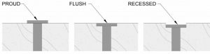
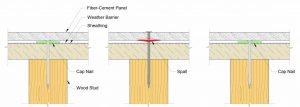
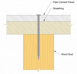 [5]
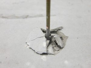
[5]In general, laboratory mock-up methods were used to simulate nail installation in the field. Figure 3 depicts the general configuration considered by the test program, which includes a wood stud, exterior sheathing, and the fiber-cement panel. Nails were installed in the center of the specimens in the proud, flush, or recessed condition (Figure 4). A 15-degree coil siding nailer was used for pneumatic installation of the nails. Pneumatic nailing is a common installation approach due to its efficiency compared to hand nailing. The specific pneumatic nailer used for specimen fabicration was selected due to its representation of common commercial pneumatic nailers, availablity to the authors, and compatiblity with the coil siding nails selected for the test program. The test program also considered the interface between the exterior sheathing and the fiber-cement panel. When sheet-type weather barriers, such as those fabricated from spun-bonded olefin fibers, are included in the wall assembly, installers often use cap nails to mechanically fasten the sheet to the exterior sheathing. The cap nails create a gap between the exterior sheathing and the back surface of fiber-cement panels, which, according to hypothesis, influences the size of the spall on the inboard face of the fiber-cement board created during nail installation (Figure 5).
The test program considered five cases that incorporated variations in the nail head condition and substrate configuration (i.e. the gap between the substrate and the fiber-cement panel). Items 1 through 3 describe the five test cases in detail.
Case 1
Specimens were pre-drilled at the nail locations, and nails were then installed proud within the holes by hand. This case was used as a control.
Case 2
 [6]
[6]Specimens were not pre-drilled and were placed directly against the exterior sheathing of a mock-up frame simulating a typical wood-framed, gypsum-panel-sheathed stud wall and fastened using the pneumatic nailer adjusted such that the nail heads were proud.
Case 3
Specimens were not pre-drilled and were placed against cap nails used for the mechanical attachment of a sheet-type weather barrier installed over the exterior sheathing of a mock-up frame to simulate a typical wood-framed, gypsum-panel-sheathed stud wall. The cap nails created an approximately 3.2 mm (0.13 in.) gap between the sheathing and the fiber-cement specimen. Nails were then installed using the pneumatic nailer, adjusted such that the nail heads were:
• Proud (case 3.a);
• Flush (case 3.b); or
• Recessed by approximately 0.51 mm (0.02 in.) (case 3.c).
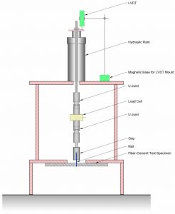
Each strength test was performed by inserting the test specimen into a test machine with the nail pointing up through a 76-mm (3-in.) diameter round hole in a steel plate used as a restraint. The circumference of this opening provided support to the specimen during the test. A drill chuck was used to grip the shaft of the nail, and a load was applied by the test machine via self-aligning linkages. The load was continuously applied at a constant displacement rate and monitored by a 113-kg (250-lb) capacity load cell. Crosshead displacement was electronically monitored with a linear variable differential transformer (LVDT). A data acquisition system interfaced with a personal computer digitally recorded the data. The failure mode and maximum load at which the nail head pulled through the specimen was recorded for each test. Figure 6 is a schematic sketch of the test setup.
For each product, six specimens were tested for each of the five test cases, for a total of 30 tests per product.
 [7]
[7]Test results and discussion
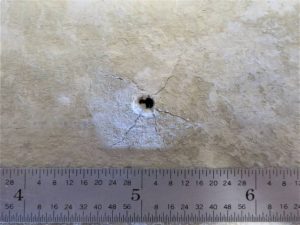
In general, the installation of nails using the pneumatic nailer (cases 2 and 3) created a spall on the inboard face of the test specimen. The spall was typically more pronounced for case 3 because of the unconstrained condition of the fiber-cement specimen due to the gap created by the cap nails. Figure 7 shows a typical spall created during nail installation. This spalling effectively reduces the cross-section of the specimen available to resist pull-through of the nail head. The cross-section is further reduced when the nail is overdriven (i.e. installed flush or recessed).
The failure mode for all tests involved additional spalling of the inboard face of the test specimens, resulting in a decrease in the measured load (see Figure 6). In some instances, the nail head completely pulled through the panel; however, tests were usually terminated when the load bearing capacity at the nail location was irrevocably lost.
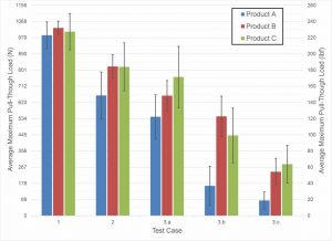
Table 2 summarizes the data from the test program. For each set of six tests, the average maximum load, standard deviation, and coefficient of variation (abbreviated Avg. Max. Load, Std. Dev., and Coeff. of Var., respectively) are presented. To check for outliers, a Dixon’s Q test was performed for each set of six tests. With six values and at 95 percent confidence, a Q value of 0.625 was used. The only outlier identified was one of the Product A, case 3.c specimens. This outlier was omitted from the statistical data presented in Table 2. Figure 9 is a bar graph indicating the average maximum pull-through load for each product and test case. The error bars indicate plus and minus one standard deviation.
Table 2 – Summary of nail head pull-through test data.
| Test Case |
Nail Head Condition |
Product A | Product B | Product C | ||||||
| Avg. Max. Load |
Std. Dev. |
Coeff. of Var. |
Avg. Max. Load |
Std. Dev. |
Coeff. of Var. |
Avg. Max. Load |
Std. Dev. |
Coeff. of Var. |
||
| 1 | Proud | 992 N
(223 lbf) |
73.6 N
(16.5 lbf) |
7.4% | 1032 N
(232 lbf) |
37.2 N
(8.4 lbf) |
3.6% | 1012 N
(228 lbf) |
99.9 N
(22.5 lbf) |
9.9% |
| 2 | Proud | 661 N
(149 lbf) |
128.9 N
(29.0 lbf) |
19.5% | 820 N
(184 lbf) |
64.7 N
(14.5 lbf) |
7.9% | 818 N
(184 lbf) |
131.6 N
(29.6 lbf) |
16.1% |
| 3.a | Proud | 544 N
(122 lbf) |
121.8 N
(27.4 lbf) |
22.4% | 660 N
(148 lbf) |
83.1 N
(18.7 lbf) |
12.6% | 762 N
(171 lbf) |
168.5 N
(37.9 lbf) |
22.1% |
| 3.b | Flush | 164 N
(37 lbf) |
107.5 N
(24.2 lbf) |
65.4% | 546 N
(123 lbf) |
111.1 N
(25.0 lbf) |
20.3% | 441 N
(99 lbf) |
150.5 N
(33.8 lbf) |
34.1% |
| 3.c | Recessed | 84 N
(19 lbf) |
46.6 N
(10.5 lbf) |
55.5% | 242 N
(54 lbf) |
72.1 N
(16.2 lbf) |
29.8% | 284 N
(64 lbf) |
103.5 N
(23.3 lbf) |
36.5% |
 [8]
[8]For all three products, the average nail head pull-through resistance was greatest for the control case (case 1). Because holes for the nails were pre-drilled and the nails were installed proud, there was no reduction to the cross-section due to overdriven nail conditions or spalling on the inboard faces of the specimens. Conversely, the average pull-through resistance was consistently the least when the specimens were prepared over the substrate with the cap nails, and the nails were installed in the recessed condition (case 3.c). This is due to the section loss that results from the spalling of the inboard face of the specimen during the pneumatic installation of the nail combined with the local crushing introduced by the recessed condition of the nail head. As expected, the less sound material present around the nail head, the lower the load required to pull the nail head through the panel.
The following items further describe the reductions observed in the average nail head pull-through resistance test data for various test cases:
 [9]
[9]• When comparing the effect of spalling (case 1 to case 3.a), the percent reductions in pull-through resistance were approximately 45, 36, and 25 percent for Products A, B, and C, respectively;
• When comparing the effect of nail head condition (case 3.a versus case 3.c), the percent reductions in pull-through resistance were approximately 85, 63, and 63 percent for Products A, B, and C, respectively; and
• When comparing the best-case scenario (case 1) to the worst-case scenario (case 3.c), the percent reductions in pull-through resistance were approximately 92, 77, and 72 percent for Products A, B, and C, respectively. For each product tested, the pull-through resistance was reduced by at least 725 N (163 lbf) when comparing these two scenarios.
 [10]
[10]Overall, the test data indicates inboard face spalling results in significantly reduced pull-through resistance. Furthermore, when considering the effect of nail head condition, the pull-through resistance is further reduced upon nail head penetration of the outermost material layer (i.e. from the proud to flush condition) and reduced further yet as the nail head penetration depth with respect to the panel face increases (i.e. from the flush to recessed condition). Both the face spalling and nail head condition parameters contribute to variations in pull-through resistance and should be carefully considered during design, specification writing, and installation.
Conclusion and recomendations
 [11]
[11]Fiber-cement-based products used in construction are not uncommon in the industry; however, limited information is available regarding their material behavior. Specifically, as a cladding material, specifiers and installers should be aware of the apparent sensitivity to variations in the substrate configuration and nail head installations, and understand the consequences of not installing in accordance with the manufacturer’s written instructions. Based on the independent laboratory results presented, the following concluding remarks are presented:
• Even subtle differences in the position of nail heads relative to the cladding panel surface can have substantial consequences on the cladding material’s capacity to resist applied loads. This is particularly important if pull-through resistance is already reduced due to unconstrained spalling on the inboard face of the fiber-cement panel, as is the case for wall assemblies that include cap nails which create a gap between the exterior sheathing and the panel;
• Construction specifiers should consider the sensitivity of pull-through resistance to the nail head condition and substrate configuration. As such, it may be prudent to specify a thicker panel and/or additional nails, based on the design criteria, to account for potential reductions to the rated load resistance due to installation errors (e.g. overdriven fasteners). This would be particularly important for projects with high design wind loads;
• When installing fiber-cement-based products with nails, builders should periodically calibrate their pneumatic nailers on a representative mock-up to avoid flush and recessed head conditions. Requirements for periodic calibrations should be clearly identified in the project specifications; and
• Field quality control measures should be implemented on all construction projects using fiber-cement-based materials. Such measures should be clearly identified in the project specifications and may include the construction of mock-ups for training the installers in accordance with the manufacturer’s written instructions and periodic inspections of installed nail head conditions.
Understanding the material behavior of fiber-cement-based products and the implementation of practices that reflect this understanding is critical to successful installations.
Author
 Jacob W. Arnold is the manager of testing services at Raths, Raths & Johnson, Inc. (RRJ), a nationally recognized engineering, architecture, and forensics consulting firm. His experience includes laboratory testing of building materials, in situ field quality control testing, and implementation of monitoring programs to investigate the effects of environmental conditions and the performance of building components. Arnold can be reached at jwarnold@rrj.com.
 Colin P. Rueb is a structural engineer at RRJ and is experienced in structural investigations and material analyses of various building materials, with emphasis on concrete construction. His background includes condition surveys, field and laboratory testing, structural analysis, and finite element modeling of distressed facade systems, building components, and various structures. Rueb can be reached at cprueb@rrj.com.
 Kurt Hoigard is the President of RRJ and responsible for the leadership and oversight of the firm’s consulting and testing services. He has specialized in the investigation and repair of distressed and deteriorated structures and the performance of building materials and systems, and consults in the areas of structural analysis, complete collapse, design peer review, water leakage investigation, and expert witness testimony. Hoigard can be reached at krhoigard@rrj.com.
- [Image]: https://www.constructionspecifier.com/wp-content/uploads/2021/12/Fiber-cement-opener.jpg
- alternatives: http://www.webmd.com/connect-to-care/asbestos/asbestos-exposure-brief-history.
- coating: http://www.archdaily.com/914944/how-are-fiber-cement-panels-created.
- [Image]: https://www.constructionspecifier.com/wp-content/uploads/2021/12/Fig_02.jpg
- [Image]: https://www.constructionspecifier.com/wp-content/uploads/2021/12/Fig_03.jpg
- [Image]: https://www.constructionspecifier.com/wp-content/uploads/2021/12/Fig_04.jpg
- [Image]: https://www.constructionspecifier.com/wp-content/uploads/2021/12/Fig_05.jpg
- [Image]: https://www.constructionspecifier.com/wp-content/uploads/2021/12/Fig_06.jpg
- [Image]: https://www.constructionspecifier.com/wp-content/uploads/2021/12/Fig_07.jpg
- [Image]: https://www.constructionspecifier.com/wp-content/uploads/2021/12/Fig_08.jpg
- [Image]: https://www.constructionspecifier.com/wp-content/uploads/2021/12/Fig_09.jpg
Source URL: https://www.constructionspecifier.com/fiber-cement-panel-siding-nail-head-pull-through-resistance/