

ASTM E119 testing procedures involve exposing the assembly to increasing furnace temperatures based on the standard’s specified time-temperature curve. Some assemblies must also withstand a hose stream test to evaluate the assembly’s ability to remain intact during fire conditions. A full list of specified furnace temperatures and acceptance criteria for various types of assemblies can be found in ASTM E119.
Component Additive Method for calculated fire resistance
ASTM E119 is also used as a reference for comparing the fire resistance of assemblies and materials. As detailed in “Analytical Methods for Determining Fire Resistance of Timber Members” by Robert H. White in the SFPE handbook, the Component Additive Method (CAM) was developed by the National Research Council Canada (NRC) to determine the fire-resistance ratings of various building elements. CAM was created by correlating data from fire tests of light-frame wood assemblies to ones tested to ASTM E119.
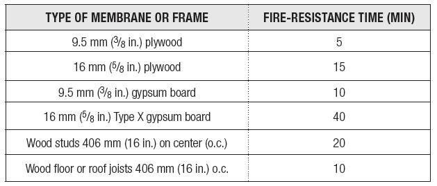
Through CAM, the protective membranes and framing of an assembly are assigned individual fire-resistance times. The total fire-resistance rating of the assembly is determined by adding the times allotted to each individual component. CAM is only applicable to light-frame wood assemblies and is limited to the specific components tested as part of NRC’s research. Examples of fire-resistance times assigned to various light-frame components are summarized in Figure 1. For additional fire-resistance times and more information on CAM, consult 2018 IBC 722.6, “Wood assemblies,” and “Analytical Methods for Determining Fire Resistance of Timber Members” by Robert H. White.
Calculating fire-resistance ratings using CAM is allowed by IBC to demonstrate the fire ratings of light-frame wood, and can be used in lieu of specifying an assembly tested to ASTM E119 (2018 IBC 703.3 and 722.6). Although CAM can be used to obtain fire-resistance times between 20 and 90 minutes, IBC limits the approach for assemblies with a maximum fire-resistance rating of one-hour (2018 IBC 722.6.1.1, “Maximum fire-resistance rating”). Additionally, IBC 722.6 limits the application of CAM to wood framing spaced a maximum of 406 mm (16 in.) on center (o.c.) and to wood joist construction only.
Calculated fire resistance using the National Design Specification for Wood Construction
Since the CAM approach is only applicable to light-frame wood assemblies, alternate methods must be used for mass timber assemblies. IBC also allows the use of chapter 16, “Fire Design of Wood Members,” of the American National Standards Institute (ANSI)/AWC, National Design Specification (NDS) for Wood Construction, to calculate the fire resistance of exposed wood members (2018 IBC 722.1, “General”). NDS procedures are an expansion of the calculation methods originally developed by T.T. Lei at NRC in the 1970s. Lei’s methods were first recognized by model building codes in the United States in 1984 and were adopted by all the three legacy codes organizations—the Building Officials and Code Administrators International, Inc. (BOCA), International Conference of Building Officials (ICBO), and Southern Building Code Congress International (SBCCI). More information on the development and history of the NDS calculation procedures can be found in AWC’s “Technical Report No. 10.”
Overview of the NDS calculation method
The NDS method for determining fire resistance is based on a calculation of the char layer depth at the time of required fire-resistance (e.g. one-hour). A nominal char rate of 0.6 mm/min (1.5 in./h) is used to represent standard fire exposure (i.e. ASTM E119 exposure). Using the nominal or a selected char rate, and the equations provided in chapter 16 of NDS, designers can calculate the char depth in a given member.
While NDS calculations use a nominal char rate, the corners of rectangular members experience increased charring due to the impinging heat transfer from two directions. As a result, the corners of wood members become rounded during a fire. Additionally, the preheated zone has reduced structural capacity due to elevated temperatures. As a result of these conditions, NDS specifies the use of an effective char depth that is 20 percent deeper than the calculated level. Using the effective char depth to determine the reduced cross section of the member, chapter 16 of NDS outlines procedures for determining the remaining average ultimate strength of the member. If the ultimate strength is sufficient for the supported loads, the member is considered to be capable of providing the applicable fire-resistance rating.
Comparison of NDS calculations and fire tests of wood members
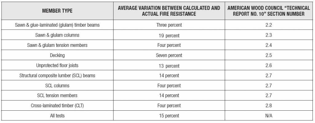
Part II of AWC’s “Technical Report No. 10” compares approximately 145 fire tests of wood members to the calculated fire resistance of the member using chapter 16 of NDS. The tests included both large timber members as well as smaller, light-frame options. As shown in Figure 2, the calculated fire-resistance times were within three to 19 percent of the measured fire resistance of the members. The fire test results illustrate the NDS calculation procedure is capable of accurately estimating the fire resistance of exposed wood members.

