Floor vibration control strategies for adaptive reuse of buildings into labs
by arslan_ahmed | January 11, 2024 11:58 am
 [1]
[1]By Brad Pridham, PhD, P.Eng., Michael Wesolowsky, PhD, P.Eng., Rabih Alkhatib, PhD, P.Eng., and Sami Rahman, M.A.Sc., P.Eng.
Over the past five years, the commercial real estate industry has seen a surge in the acquisition of properties to be renovated as laboratory space for the health sciences sector. This has involved renovations of buildings across North America to create tenant space suitable for housing state-of-the-art research tools and programs.
A key challenge for architects and engineers has been the development of strategies for vibration control, where it is necessary to achieve a base level of performance suitable for life sciences. Achieving success often involves analyzing the vibration performance of the base structural system, followed by evaluating various options to ensure alignment with performance objectives.
Vibration sources of concern
Floor vibration problems in reuse scenarios are typically caused by:
- Occupant activity, such as walking, running, dancing, and exercising, which results in dynamic forces transmitted to the floor during each footfall.
- Building services, such as pumps, fans, and generators with vibrations during operation that transmit to the structure, resulting in structure-borne noise and tactile levels of vibration.
- Environmental sources, such as roadway and railway traffic and vibration activity in nearby buildings that transmit through the ground into the building.
While occupant activity is arguably the most problematic source of vibration on supported floors, it is not uncommon during building reuse for spaces to be sited close to building equipment or exterior roadways, resulting in increased exposure to vibrations.
 [2]
[2]Vibration criteria
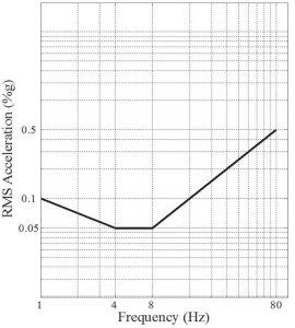
Criteria for floor vibration are specified based on the space’s use and occupancy. Many of these evolved from the isoperceptibility curve, which represents the threshold of vibration perception for humans (foot-to-head vibration direction) over the 1 to 80 Hz frequency range.
The y-axis is the root-mean-square (RMS) vibration acceleration level—typically computed for a one-second time window. Floor vibration levels having magnitudes greater than this curve will be perceptible to most people. The flat portion of the curve, between 4 and 8 Hz, represents the frequency range where people are most sensitive to vibration.
The isoperceptibility curve is commonly referred to as the “ISO base curve” because it is defined in the International Organization for Standardization (ISO) 2631-1, Mechanical Vibration and Shock–Evaluation of Human Exposure to Whole-body Vibration: Part 1: General Requirements. It serves as the basis for many vibration specifications (Figure 1).
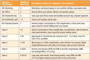
Floor vibration specifications for spaces housing sensitive equipment, or procedures are commonly expressed in units of RMS velocity (e.g 10e-9 in/s or µin/s). The thresholds for sensitive equipment are specified as fractions of the base curve (also referred to as the ISO–operating theatre curve in this context, as it is commonly specified for the design of general surgical suites).
 [3]
[3]Each curve is assigned a vibration class, representing a category of equipment/procedures appropriate for the specified environment—in other words, vibration levels in the environment should not exceed the assigned threshold. Vibration classes C through E are slight modifications of the base curve, with more stringent requirements at frequencies between 1 and 8 Hz, accounting for the heightened sensitivity of ultra-low vibration equipment in this frequency range (Figure 2).
In commercial multi-tenant laboratory buildings, owners may specify, and in some cases, promote the vibration performance of the building as a strategy to attract tenants. Marketing materials may include references to the standard vibration criteria, such as indicating a Class A vibration performance (2,000 micro-in. per second) in sectors A, B, and C, and Class B performance (1,000 micro-in. per second) in sector D. These criteria are commonly recognized by laboratory operators, providing a clear indication of the types of equipment and procedures the building can effectively accommodate.
 [4]
[4]Vibration performance assessment
Repurposing floors for laboratory use often requires an assessment by a vibration engineer to assess the performance of the existing structure and to determine the feasibility of achieving the vibration goals of the project. An assessment should include measurements at various locations on the floor(s) and must consider all relevant site vibration sources. With this information, it is possible to produce a map of vibration classes for various areas of the building. The base performance provides the owner and design team with insights into the divergence of the current performance from the target criteria, indicating whether remedial measures are necessary.
It is standard practice to measure floor responses to various pedestrian pacing rates (e.g. slow, moderate, fast), as well as to perform dynamic modal tests to identify vibration frequencies and damping ratios. Where environmental sources are a concern (e.g. railway traffic), the worst-case impacts to performance should be quantified and feasibility of mitigation verified. Any major building services to remain following renovations should also be considered as these sources may be particularly problematic for many laboratory tools (e.g. MRI, high-resolution microscopes, NMR, etc.).
Changes to the existing vibration performance of the building should be anticipated when there will be significant changes to massing and partition layouts. Floor areas that previously supported heavy office furniture or filing cabinets and were highly partitioned may be repurposed as laboratory modules with little-to-no partitioning and lower superimposed structural loads. In such cases, the floor may become livelier due to reduced mass and damping. Conversely, the introduction of partitions spanning slab-to-slab through mid-bay will generally result in lower vibration levels following reuse. These changes can be significant and may warrant additional/supplemental vibration control measures to achieve performance objectives.
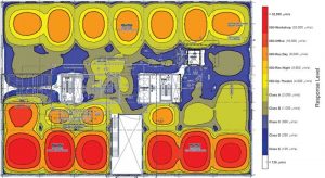
Numerical finite element modeling (FEM) is a useful tool for estimating vibration performance, considering the effects of both structural and non-structural elements associated with planned reuse. The model is developed and calibrated using data which is collected during the measurement survey. The dynamic parameters that are outputs from FEM are used to generate response maps (heat maps) that illustrate the expected distribution of vibration levels on a floor. They can be an effective tool for evaluating layouts and control strategies and for identifying zones of high or low vibration response.
Vibration control strategies
Controlling unwanted floor vibration has become a growing challenge for structural engineers, building owners, and laboratory operators. Traditional measures involve increasing section sizes, modifications to existing sections to improve stiffness, and increasing concrete thickness. These strategies can result in substantial material costs and added embodied carbon.
Isolation tables and platforms are very effective for controlling incoming support motions at the base of the equipment, but they are not a universal solution. Generally, they can only be used on the equipment for which they are designed for and can be susceptible to resonances from motions of the supporting floor. They are best suited to slab-on-grade supports or sufficiently stiff structural floors that have vibration frequencies well separated from the isolation frequency. They should not be used as a catch-all for vibration control, and mitigation measures that target the source of vibration (i.e. source isolation, location of sensitive spaces away from corridors, service spaces, and environmental sources) or the vibration path (i.e. the structural system) should be part of the solution.
Supplemental dampers—TMDs and AMDs
Supplemental dampers are devices that oppose the motion of a floor that has been excited by an externally applied force (e.g. footfalls and rhythmic activity, ground-borne vibrations). If designed and implemented properly, they achieve three goals: maintain structural motion levels below targeted criteria, optimize remedial structural measures and the number of low vibration zones, and reduce the cost of adaptive reuse due to fewer and/or smaller structural elements.
Tuned mass dampers (TMDs) are an example of passive vibration control using devices that do not require any power and are generally maintenance free for the life of the building. As the name implies, TMDs are composed of a mass supported by a spring and viscous damper that can be tuned to the specific vibration frequency of the floor. Traditionally, TMDs have been used to control perceptible and excessive motions from wind loading and crowd movement, but recent research by the authors has highlighted the viability of TMDs for use in low-vibration environments, such as laboratories.
This viability was demonstrated by successful implementation of a TMD solution during the design of a new multi-story laboratory building. The performance objective was vibration Class A in all labs. A total of 166 TMDs were installed throughout the building, with 100 percent of the labs achieving Class A, and approximately half the labs achieving the more stringent Class B. Equally important to the performance was the cost savings on steel framing: approximately $5 million USD.
Active mass dampers (AMDs) are a recently developed active vibration control device that addresses some of the shortcomings with TMDs. TMDs control a single mode of vibration of the floor, must be spatially located at the point of maximum deflection, are typically heavy (upward of 1,814 kg [4,000 lb]), and require structural connections to the floor. Whereas AMDs can control motions over a wide frequency range (thus addressing multiple modes of floor vibration), they can be located away from peak deflection points, and are very light (66 kg [147 lb]).
 [5]
[5]Unlike TMDs, AMDs require power and internet connectivity for operation and maintenance access. However, the current draw is very low (equivalent to a laptop), and a great amount of research has gone into developing a robust design that is essentially maintenance free. A key feature is these devices are plug-and-play, with very little tuning required. Being light and compact, the devices can be easily installed to the web of a beam or anchored directly to the floor (top or bottom).
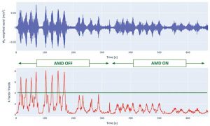
Example time traces from the AMD installation are shown in Figure 3 for both the “AMD off” and “AMD on” conditions. The top plot is the acceleration versus time trace, and the bottom plot is the response factor, which is defined as the multiple of the ISO base curve (i.e. R=4 indicates levels four times the ISO base curve level). A fourfold reduction in response factors is observed with the AMD on, going from R=8 (ISO–workshop) to R=2 (ISO–residential night).
The choice between TMD and AMD is generally project specific. By proper design, both technologies effectively reduce vibrations and therefore, higher performance objectives can be attained. Response maps can be used in conjunction with TMD or AMD models to provide an understanding of where higher performance can be achieved. This can be very beneficial for adaptive reuse projects where combined structural-TMD/AMD solutions can be developed to optimize cost and performance.
Specifying vibration controls
When required, supplementary damping devices can be included in Division 10 – Specialties on building projects. These specifications will typically be developed by the vibration engineer as they require specialized knowledge and information. While some solutions are offered “off the shelf,” more often, they must be customized for the project. As a minimum, a well-written specification should include the following information:
- Number and locations of TMDs/AMDs.
- Total weight and anchorage forces for installation points,
for each device. - Access requirements for power, ethernet, maintenance,
as appropriate. - A list of qualified suppliers.
- Commissioning and performance verification test methodology and reporting requirements (factory and field, as appropriate).
- Requirements for submittals, such as shop drawings and performance verification test reports.
 [6]
[6]Keys to a successful project
When control of vibration is important to the success of a project, a qualified vibration engineer should be engaged to assist with solution development. The first step is to assess the performance of the structure. A measurement survey is recommended, when possible, as data from the site is helpful to understanding the dynamic properties of the system and can be used to develop a computer model of the floor. With this information available, various control solutions can be evaluated to determine the best option for the project. The vibration engineer can assist the team with implementing the solution in the design documents and specifications, quality control (QC) testing, installation, and commissioning.
Conclusion
Successful management of floor vibration in building reuse scenarios requires an understanding of existing vibration conditions, vibration criteria targets, and feasibility of mitigation options. A qualified vibration engineer can assist project teams with assessment and development of solutions. As results from such an assessment can have substantial impact on project costs and timelines, the floor vibration control strategy should be developed as early as possible for the project. Problematic vibrations are costly and difficult to fix once a facility is completed and occupied.
Authors
 Brad Pridham, Ph.D., P.Eng., is the vice-president with New York-based Thornton Tomasetti. Since 2004, he has been actively involved with the vibration design of various structures across the globe.
 Michael Wesolowsky, PhD, P.Eng., is a principal in Thornton Tomasetti’s Mississauga, Canada, office. A senior member of Thornton Tomasetti’s acoustics, noise, and vibration control engineering team, he has considerable experience in analysis, project management, and design.
 Rabih Alkhatib, PhD, P.Eng., is a senior associate in Thornton Tomasetti’s Mississauga office in Canada.
 Sami Rahman, M.A.Sc., P.Eng., senior project engineer in Thornton Tomasetti’s Mississauga, Canada, office.
- [Image]: https://www.constructionspecifier.com/wp-content/uploads/2024/01/T_230905_N9-5.jpg
- [Image]: https://www.constructionspecifier.com/wp-content/uploads/2024/01/Figure-1.jpg
- [Image]: https://www.constructionspecifier.com/wp-content/uploads/2024/01/figure-2-table-for-vibration-specs.jpg
- [Image]: https://www.constructionspecifier.com/wp-content/uploads/2024/01/Figure-3.jpg
- [Image]: https://www.constructionspecifier.com/wp-content/uploads/2024/01/Figure-6.jpg
- [Image]: https://www.constructionspecifier.com/wp-content/uploads/2024/01/floor-vibration-control.jpg
Source URL: https://www.constructionspecifier.com/floor-vibration-control-strategies-for-adaptive-reuse-of-buildings-into-labs/