By Danielle DiDomizio, P.E., Amarantha Quintana-Morales, AIA, and Matthew Normandeau, P.E.
The design of contemporary cavity wall assemblies is the result of a century of trial and error. During the transition from mass masonry walls to the “four barrier” (i.e. water, air, vapor, and thermal barrier) assemblies of today’s construction, the “early veneer walls” constructed between the mid- to late-20th century emerged.
These assemblies lack many necessary components that comprise an effective building enclosure system. Issues related to this wall assembly have led to numerous buildings requiring extensive repairs, and in some cases, full recladding, or even demolition.
Transition from mass to today’s veneer
Mass masonry construction was commonly used in the U.S. prior to 1890. In mass masonry structures, the exterior walls are constructed with brick, clay tile, or stone masonry tied together with mortar, and are load bearing, supporting each floor slab. The introduction of steel-framed construction, and the desire to build taller and more economical structures quicker, led to the development of transitional masonry wall systems between the 1890s to the mid-1900s. These structures consist of a steel frame or, less often, a concrete frame, infilled with brick or hollow clay tile. The masonry cladding encases and is supported by the structure and is tied back to it by brick headers and/or metal masonry ties. Transitional masonry construction resulted in separation between the inner (backup wall) and outer masonry wythes by a grouted collar joint. However, the lack of an effective waterproofing system and accommodations for differential expansion between the masonry and structural frame caused masonry deterioration and steel corrosion over time. This led designers toward masonry cavity wall systems and veneer wall assemblies.
Cavity walls were being constructed in the U.S. as early as 1850, primarily as exterior load-bearing walls in one- and two-story buildings, but were not officially recognized in building codes until 1937.1 The term “cavity wall” was originally used to refer to a wall consisted of two wythes of masonry separated by an air space. The exterior wythe, typically brick, and interior wythe, which could comprise brick, structural clay tile, or concrete masonry units (CMU), were connected by metal ties. The exterior wythe of a cavity wall was designed to resist loads by internal stresses within the wythe, and both the exterior and interior wythe were designed to resist out-of-plane loads.
Records of veneer wall assemblies existed in the U.S. as early as 1899;2 however, these assemblies were typically used in the construction of wood-framed buildings that were only a few stories tall. By the mid-20th century, veneer systems with masonry backup were becoming common for high-rise buildings. These wall systems separated the exterior masonry veneer and interior backup with an air cavity rather than a grouted collar joint seen in transitional masonry construction. Veneer walls differentiated from cavity walls by their structural design. The exterior wythe in a veneer wall was designed to transfer most loads to the backup wall and building structure. The use of metal ties and steel relieving angles was required to transfer those loads. Membrane and/or metal flashings were introduced to drain water from the air cavity where it was interrupted by the angles. Vertical and horizontal expansion joints were also introduced into these systems.
Today’s definition of “cavity wall” construction also consists of masonry units, concrete, or a combination of both, arranged to provide an airspace within the wall, and in which the inner and outer parts of the wall are tied together with metal ties.3 However, contemporary cavity walls also typically include insulation and an air/water/vapor barrier to meet today’s more stringent code requirements.
Shortcomings of an early veneer wall
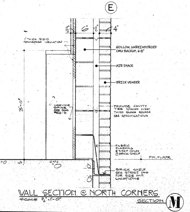
While looking at the different components of an early veneer wall system, it is clear how the issues associated with those systems inspired updates to the building code and what the AEC now knows as a veneer wall. Shortcomings of these veneer wall assemblies are summarized herein, using a generic case study building to illustrate the resulting performance problems and remedial options. The case study building is 14 stories, constructed in the 1970s, with a reinforced cast-in-place concrete structure, CMU backup walls, and brick veneer. The exterior wall assembly consists of the following components from exterior to interior: standard 76 to 15 mm (3 to 0.6 in.) brick veneer, 50 mm (2 in.) air space, 152 to 208 mm (6 to 8 in.) CMU, and 25 mm (1 in.)-thick rigid insulation (Figure 1). Cavity ties include horizontal metal truss reinforcing spaced every third CMU course, and relieving angles are located at each floor with fabric flashing and weep holes above.
Backup construction and ties
Concrete, CMU, wood studs, steel studs, and light structural steel (cold-formed) members were all used as backup materials in early veneer wall assemblies. As experiments with different backup materials evolved, designers learned each backup wall material influenced overall wall performance in different ways, and industry standards and requirements were adapted to these differences. Part of the appeal of veneer walls was the isolation of the backup walls from the building structural frame. This allowed for thinner, lighter, and more cost-effective backup walls infilled within the structural frame. These walls were typically unreinforced and not always positively attached to the structure, despite building code requirements as early as the 1950s to provide anchorage to the structure.4
The design of early veneer walls assumed the backup wall would resist all loads. The 1958 Uniform Building Code (UBC), section 2901 and 2902 states the veneer “shall not be assumed to add to the strength of any wall … to resist horizontal forces … [or to] support any vertical load other than the dead load of the veneer above.”5 However, in reality, the distribution of loads between the veneer and the backup was more complex and depended on the design and performance of the ties and the stiffness of the veneer and the backup. The design and spacing of metal ties in veneer walls initially evolved through empirical design. The 1958 UBC, section 2902, required the use of corrosion-resistant metal ties, with one tie per 0.19 m2 (2 sf) of wall area spaced maximum 609 mm (24 in.) on center (o.c.). Dead load support was to be provided every 3 m (12 ft) vertically above 6 m (20 ft) from grade.6 In practice, tie spacing in veneer walls with masonry backup was constructed based on the spacing of masonry headers, whereas tie spacing in walls with metal stud backup evolved from designs used with wood stud backup. In both cases, the veneer wall assemblies were being used in different applications (e.g. larger spans, taller buildings) than their predecessors without testing to verify their performance. As a result, the 1970s, 1980s, and 1990s saw an increase in the number of reported problems associated with early veneer wall structural performance.
Multiple issues related to the backup wall and ties were observed in the case study building, as they are common in early veneer walls. Using ground-penetrating radar (GPR), the CMU backup walls were confirmed to be ungrouted, unreinforced, and not mechanically connected to the concrete structural frame. In fact, open gaps were apparent between the CMU and concrete spandrel beams at several exterior exploratory openings. The net tensile stresses were calculated in full-height walls per the original code of construction and the current code and then compared to the tensile stresses allowed by each code. The findings showed the demand-to-capacity (DCR) ratio using the current code was more than one, indicating the walls are overstressed when subject to code-prescribed loads. The original code of construction did not include values for allowable tensile stress, which was interpreted to mean that tensile stresses were not permitted in unreinforced masonry.
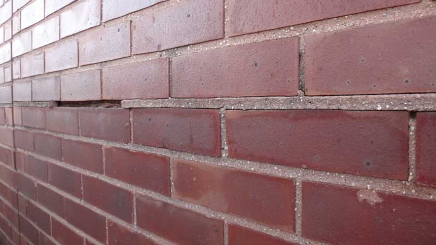
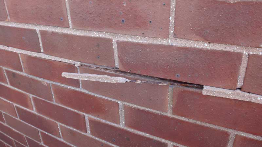
The analysis indicated the CMU backup walls were not adequate to support the design wind loads prescribed by either the original code of construction or current codes. There was no evidence the above deficiencies compromised the structural performance of the CMU backup walls, which had been in place for more than 40 years. This is likely due to the building not having exposure to a design wind event and some inherent factor of safety. However, through continued work on the building, several locations of horizontal displacement of the brick veneer below relieving angles were observed (Figure 2a, page 21). This displacement, which was up to 50 to 12 mm (1 to 0.5 in.) at one location, extended to the CMU backup (Figure 2b, page 21). The assessment concluded this displacement was caused by lack of grout and reinforcing within the CMU walls, and lack of mechanical attachment of the backup to the structure.
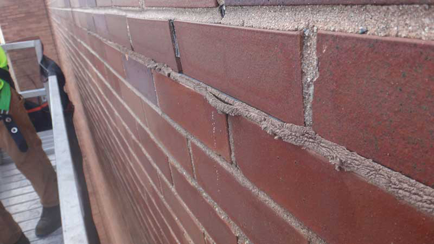
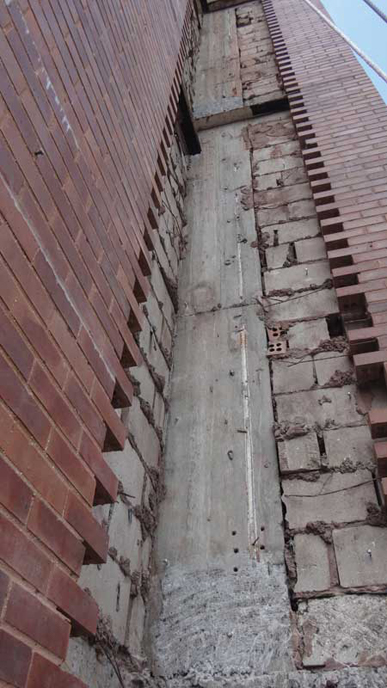
In addition, the horizontal metal truss reinforcing tying the brick veneer to the CMU backup wall at every sixth brick course had significant corrosion, despite the lab-confirmed presence of a corrosion-resistant coating. This corrosion buildup within joints caused large sections of mortar to fall from the building as the corrosion product pushed the mortar out of joints (Figure 3). Further, the truss reinforcing restricted differential movement. The corrosion product buildup also exacerbated the brick veneer horizontal displacement. The client and project team were concerned about the impact of continued corrosion on the veneer’s lateral attachment and structural integrity.
Structural deficiencies such as those found in this case study building complicate the design of repairs to early veneer walls. Even smaller local repairs must consider the potential impact to the structural integrity of the wall when the backup wall cannot be relied upon for attachment of replacement veneer or miscellaneous exterior supports for new signage or similar elements. Further, any long-term repairs for these buildings must address the backup walls’ inability to resist design wind loads. Ultimately, this was addressed in this case study project by designing a replacement cladding system that completely bypassed the existing CMU backup walls.
Provisions for expansion
The separation of the veneer from the backup wall and the backup wall from the structural frame in early veneer walls addressed some of the issues associated with differential expansion that plagued transitional masonry walls. However, it did not eliminate the need to accommodate differential movement between the different wall components. In some ways, the differential expansion of the veneer and the backup wall was amplified due to the exterior veneer’s increased exposure to temperature differentials and freeze-thaw cycles, because it lacked the thermal mass and heat transfer of solid masonry walls.7 Additionally, although brick masonry and materials that comprised the backup wall, such as concrete and CMU, all expand and contract when subjected to temperature and moisture changes, they do so at different rates, exacerbating differential movement. Moreover, as previously discussed, the design and stiffness of the ties, veneer, and backup, which affect the structural performance of the different wall components, also impact the expected movement among them.
Many early veneer walls were designed without expansion joints or included expansion joints which were not sized and/or placed to accommodate the actual movements experienced by the walls, which could include moisture- or temperature-induced expansion or contraction, structural deflection, creep, and other movement from applied loads. Expansion joint design can be complex, and guidance from codes or industry standards has been generally lacking until relatively recently. The 1985 UBC included a general requirement to consider differential movements in the design of veneer and supports,8 but this is not much different from what is included in the 2022 New York City Building Code, section 2104.9, which states masonry veneers “shall be constructed with adequate depth and width of isolation joints to prevent masonry distress induced by deflections, drifts, shortening, expansion, or other similar movements in the plane of the wall.”9 Further, expansion joint design requires concerted coordination between the structural and architectural designs, creating an additional challenge to effectively include necessary movement provisions.
The original construction drawings for the case study building showed vertical control joints at building inside corners and adjacent to some windows. Horizontal expansion joints were not shown below relieving angles. Review of documentation from previous repairs indicates multiple attempts were made to add expansion joints. Drawings and photographs from 1987 show backer rod and sealant were installed below relieving angles at select locations where cracks had developed, primarily at building corners. In 1990, the building underwent widespread exterior renovations, which included restoration of existing control joints, the addition of new control joints, and installation of horizontal expansion joints below all relieving angles.
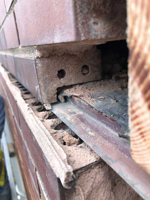
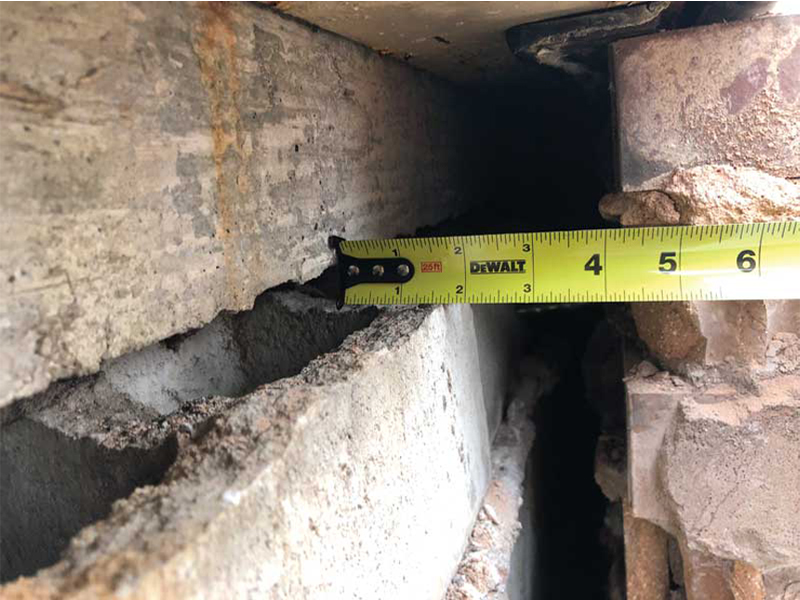
Despite these efforts, in 2017, compressed sealant at horizontal expansion joints below relieving angles (Figure 4) and horizontal displacement of brick veneer adjacent to window jambs were observed. Exploratory probes further showed compressible filler below the angles had been compacted enough to show the imprint of the cores of brick below (Figure 5). At window jambs, brick veneer extended to the interior and was installed tight to the underside of the concrete spandrel beam, with no provisions for brick growth or expansion (Figure 5). In addition, control joints at window jambs, either original to the building or installed during the 1990 renovations, did not extend through the veneer, undermining their intended purpose.
As shown by the case study, localized repairs can be performed to improve an early veneer wall’s expansion provisions; however, these repairs must be designed and constructed carefully to be effective.
Insulation (thermal barrier)
Although the use of insulation board in wall construction existed when early veneer wall systems first appeared, these wall systems did not include it within the cavity between the veneer and backup construction. Instead, if provided, it was located at the interior between studs. The cladding and air cavity of the wall system were thought to function as the thermal barriers and the full benefits of dedicated continuous thermal barriers were not known. In response to gas and oil shortages during the mid-1970s and associated concerns with building energy use, the National Bureau of Standards (NBS) developed the “Design and Evaluation Criteria for Energy Conservation in New Buildings” (Interim Energy Standard).10 This standard defined maximum thermal transmittance (U-value) requirements for building enclosure systems, including exterior walls. Insulation, typically rigid insulation boards or granular fill at the time, was added to veneer cavities by designers to address the code requirements.
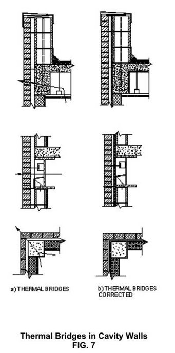
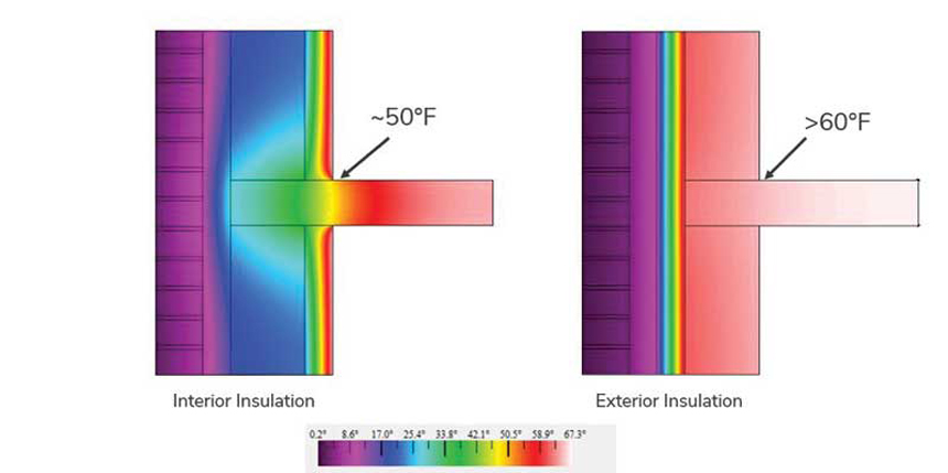
A lack of insulation within the wall cavity causes thermal bridging where interior insulation is interrupted at slab edges, columns, and parapets (Figure 6).11 This thermal bridging can lead to issues at the interior of the building, such as condensation and occupant discomfort. In the winter, humid interior air will condense on cold exterior fenestration, walls, and framing and can lead to damage to finishes, corrosion of concealed studs/structure, organic growth, and “ghosting” (localized dirt accumulation) at stud locations, among other issues. Occupant discomfort most commonly occurs at floor slabs adjacent to exterior walls. The surface temperature at these areas is often noticeably lower than just a few feet away from the exterior wall due to the interruption of interior insulation at slab edges (Figure 7) and lack of continuous insulation (c.i.).
The lack of insulation within cavities of early veneer walls is unlikely to be the primary cause of large-scale issues seen with these systems today. However, during repair campaigns that arise due to other shortcomings with this wall system, owners will most likely be required to provide insulation within cavities to meet today’s energy code requirements and improve the energy efficiency of their buildings. Whether cavity insulation is required or not is dependent on the type and size of the repair being performed.
The case study project had both localized and widespread repairs. At localized, smaller locations, the square footage of the repair area and materials replacement did not trigger the need to meet the energy code. Additionally, introduction of insulation into the wall system at these small areas would provide little benefit to the overall thermal performance of the building or occupant comfort and could impede cavity drainage. However, given that other performance concerns and the client’s needs have led to the recladding of the building, the new cladding system is designed to include insulation in the cavity to meet current energy code requirements and the client’s expectations for an energy efficient enclosure.
Air/water barriers
For early veneer walls, the air cavity between the veneer and backup wall was a form of waterproofing. Any water that passed through the veneer was expected to drain into the air cavity and out at floor lines, openings, and grade. Building codes of the day recommended keeping this air cavity free of mortar droppings and providing weep holes and flashings, such as building paper or plastic, at drainage locations. The 1958 UBC required asphalt saturated felt at backup wall construction and flashing conditions; however, there is an exception in the code that allows the omission of waterproofing at field of walls if the exterior covering (i.e. veneer) is “of approved weatherproof panels.”12 The code does not define what constitutes a “weatherproof panel,” leaving it up to the designers to make this critical judgment call. The Interim Energy Standard introduced in 1974 defined maximum allowable air leakage for exterior walls, introducing the requirement for a continuous air barrier in veneer wall construction at field of wall conditions and transitions to adjacent systems.13 This requirement for air barriers also led to continuous waterproofing membranes being introduced into exterior wall systems considering the air barriers at the time of this code release, and today, are also effective waterproofing membranes.
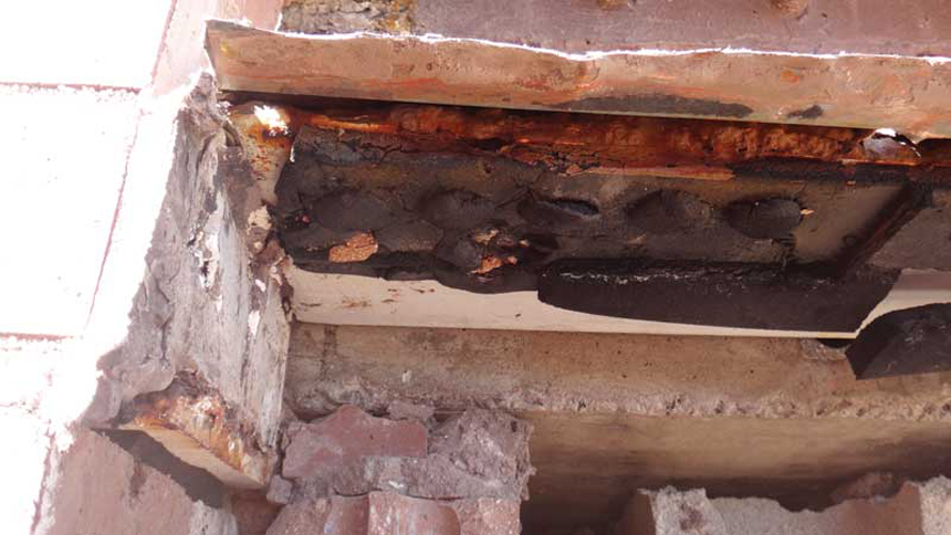
The lack of air and water barriers at field of walls often leads to air and water infiltration. Inconsistencies in masonry infilled backup walls, such as cracks and voids, will allow water that does not effectively drain down through the air gap and out at flashing locations to leak to the interior (Figure 8). Even though flashings are required at angles, flashings sometimes allowed water to leak behind the flashing onto steel angles and to the interior. Today, such situations are avoided by providing continuous, shingle-lapped waterproofing membranes at walls and transitions, and by sealing terminations to membranes, such as with termination bars and sealant and added end dams.
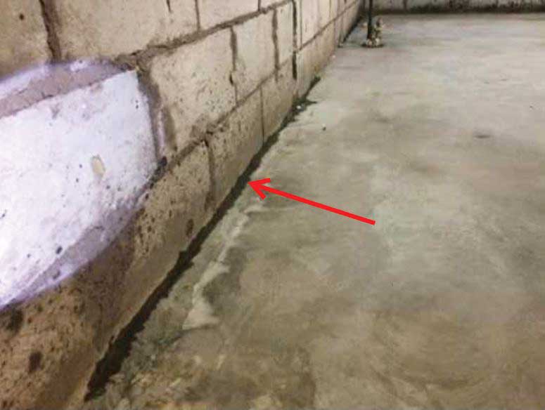
The case study building experienced water leaks due to lack of waterproofing at field of wall locations and discontinuities in the backup wall construction (Figure 9). These water leaks damaged interior finishes at multiple locations. To address these leaks, localized repairs were designed. At leak locations, the scope included cladding removal, repairing the backup wall to fix discontinuities, and providing a continuous waterproofing membrane, metal flashings at relieving angles, and replacement veneer (Figure 10). If leaks are more widespread throughout the building, localized repairs are unlikely to be a practical solution, and a full recladding may need to be performed, including waterproofing the face of the backup wall.
Conclusion
Although early veneer wall systems and cavity ball assemblies represented an improvement upon masonry systems that came before and were a beneficial step toward developing today’s contemporary rainscreen assemblies, many shortcomings associated with these systems persisted. Much of this is related to a lack of information and guidance from the beginning of their use, which resulted in substantial trial and error over the years. As with the case study building, some of these shortcomings, such as localized water leakage, can be addressed with targeted repairs, but others, including deficiencies in the backup wall, might require costly larger-scale repair campaigns, including replacement of the existing veneer.
Notes
1 Refer to Brick Industry Association (BIA), Brick Masonry Cavity Walls, “Technical Notes on Brick Construction” 21, August 1998.
2 See Masonry, Carpentry, Joinery, Scranton International Textbook Company, 1899, republished by Chicago Review Press, International Library of Technology, page 121-3.
3 For more information, see the 2022 New York City Building Code, Chapter 2.
4 Refer to the Uniform Building Code (UBC) 1958 edition, volume one.
5 Ibid.
6 Ibid.
7 Read “Proceedings of the Third North American Masonry Conference” by C.B. Monk Jr, page 1-20.
8 Refer to “Masonry Veneer,” by James E. Amrhein, Masonry Institute of America, (Los Angeles, CA, 1987), page 1-34.
9 See the 2022 New York City Building Code, Chapter 21.
10 Review the text by Jim L. Heldenbrand (ed.), “Design and Evaluation Criteria for Energy Conservation In New Buildings,” NBSIR 74-452, National Bureau of Standards (NBS), 1974. Revised in 1976. Includes a February 27, 1974 letter, bound into the document, from F. Karl Willenbrock, director of the Institute for Applied Technology, NBS, to Bernard E. Cabelus, 1973-74 NCSBCS President.
11 See Brick Industry Association (BIA), Brick Masonry Cavity Walls, “Technical Notes on Brick Construction” 21, August 1998.
12 Refer to the International Conference of Building Officials; Uniform Building Code 1958 edition, volume one.
13 Ibid.