Glass spandrels and shadow boxes: Design and construction considerations
by jason_cramp | August 11, 2021 1:51 pm
By John A. Jackson, AIA
 [1]
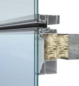
[1]Photo courtesy Simpson, Gumpertz & Heger; Illustration (right) courtesy Enclos
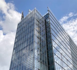 [2]It is early morning on a summer day in the mid-Atlantic. The temperature dropped overnight, and the sun is just beginning to rise, lighting the glass façades of the skyline, as the humidity and heat start to build up. When walking down the busy sidewalks during the morning commute, one might notice something odd when looking up at some of the glass skyscrapers. The spandrel glass at the floor levels appears hazy and fogged over compared to the clear windows below. It is unclear, but it looks like moisture may be trapped on the inside of the glass at the spandrels.
When walking by a few hours later during a coffee break, one notices the spandrel and vision glass now look the same—the haziness and fog have disappeared. As a result, it is fair to say one may think there was a problem with the glass earlier, but what is really going on?
Glass spandrels are a common design strategy used to opacify floor levels in building façades. These opaque glass assemblies are integrated into glazing systems, such as glass curtain walls or window walls, to provide visual continuity with adjacent vision glass to render an all-glass look to the building façade. Certain glass spandrel designs, such as shadow boxes, can also provide a greater expression of visual depth in comparison to back-painted spandrel glass or glazed-in metal panels. Spandrel assemblies typically include an exterior panel (sometimes they include an intermediate panel) and are often backed by insulation, either foil-faced or with a metal back-pan.
Although simple in concept, the physics and technical design considerations of glass spandrels and shadow boxes can be quite complex and must be carefully considered. These include the potential for heat build-up in the cavity, glass differential thermal stress, risks of cavity condensation, thermal performance, air-water-vapor seal, edge-of-slab fire safing, and accumulation of dust/debris in the cavity. Project-specific exterior climate and interior psychometric (i.e. temperature and relative humidity) conditions must also be considered. In addition, glass spandrel design must consider the method of construction of the glazing system, whether factory-glazed (e.g. unitized curtain wall or window wall) or field-glazed (e.g. stick-built curtain wall). Temporary protection during storage, transportation, and installation, as well as in-service considerations such as glass replacement must also be factored into the equation.
 [3]
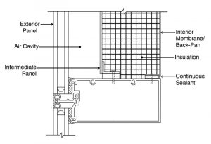
[3]Illustration courtesy Simpson, Gumpertz & Heger
Like many issues with glazing systems, design considerations for glass spandrels must be balanced carefully against the project-specific performance requirements, including considerations for construction, schedule, cost, and maintenance in-service. A summary of these important design considerations will be provided, along with recommendations through lessons learned from the author’s experience on projects using glass spandrels and shadow boxes within the building façade.
Definition of spandrels
The Fenestration and Glazing Industry Alliance (FGIA) and American Architectural Manufacturers Association (AAMA) defines spandrels as “the opaque areas of a building envelope which typically occur at floor slabs, columns, and immediately below roof areas.” Like a glass panel, spandrel assemblies are often ‘glazed into’ the framing (e.g. aluminum mullions) of glazing systems. Spandrels typically incorporate some combinations of the following components, listed from exterior to interior (Figure 1).
Exterior panel
Transparent (e.g. monolithic glass, insulating glass unit [IGU]), semitransparent (e.g. ceramic frit-coated glass), or opaque panels (e.g. opacified glass, metal panel, terracotta, stone).
Air cavity
Either vented to the exterior or sealed (unvented), typically 25 mm (1 in.) deep minimum. (Note, venting design includes items such as vent/weep hole size, quantity, location, and baffling, resulting in pressure equalization of the air cavity to the exterior and is often determined based on a combination of computational analysis, empirical test data, and past experience.)
Intermediate panel
Typically, an intermediate metal panel provides a visual surface through the glass. This is generally included when paired with transparent or semitransparent exterior panels (e.g. vision glass) to visually conceal the insulation. This would constitute a ‘shadow box’ spandrel design. In an opaque glass spandrel design, this layer would be omitted since it would be obscured by the opaque exterior panel.
Insulation
Typically, semi-rigid mineral wool.
Interior membrane/back-pan
The interior membrane can be a foil-facer membrane laminated to the insulation (functioning as an interior vapor retarder) and taped airtight to the perimeter framing. The other option is a metal back-pan (functioning as an interior air-vapor barrier or possibly, if detailed properly, as an interior air-water-vapor barrier), anchored and sealed to the perimeter framing.
Glass spandrel types and design considerations
 [4]
[4]Illustration courtesy Simpson, Gumpertz & Heger and Oldcastle Building Envelope
Terminology for glass spandrel types can vary within the industry. The following will provide some clarity and definitions. Glass spandrel types generally include:
- opaque spandrel glass;
- traditional shadow box;
- touch-mullion shadow box; and
- open shadow box.
The term ‘traditional’ shadow box is used to differentiate between other shadow box types. The following summarizes these glass spandrel types and discusses a variety of design considerations, including heat build-up, condensation risks, air-water-vapor seal, structural integrity, and access for cleaning and maintenance.
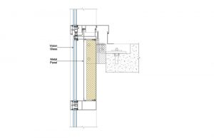
Opaque spandrel glass
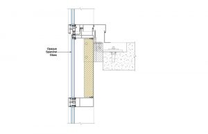
Opaque glass spandrels include an opacified glass exterior panel (Figure 2). The opaque glass panel can be either an IGU or non-insulating (e.g. monolithic or laminated glass). The glass can be opacified in a variety of ways, including a full-coverage of ceramic frit (typically on the #3 or #4 surface of an IGU), back-painted glass, opaque laminate interlayer, or an applied opacifier plastic film.
Typically, this opaque glass is referred to as ‘spandrel glass.’ Often, the spandrel glass can be a similar buildup (e.g. overall IGU thickness, low emissivity [low-e coating, typically on the #2 surface) as the adjacent vision glass to provide visual continuity across the façade. If the exterior reflectivity of the vision glass and spandrel glass are high (e.g. typically a function of the low-e coating used), the visual transition from vision to spandrel glass can appear quite seamless.
 [5]
[5]Illustration courtesy Simpson, Gumpertz & Heger and Oldcastle Building Envelope
Spandrel glass will generally block solar heat from passing through and into the building, which would otherwise need to be managed by the building’s mechanical system. Although much of the solar heat will be blocked by the spandrel glass, some heat will be absorbed by the glass and insulation (and be re-radiated). This can lead to differential thermal stress within the glass panel. For this reason, the lites of spandrel glass often need to be heat-treated.
Risk of condensation within a spandrel glass assembly will depend upon details of the construction (e.g. vented or unvented cavity, insulation thickness, detailing and sealing of the interior membrane/back-pan), the exterior climate, conditions within the cavity (e.g. built-in moisture), and the building interior psychometric conditions (i.e. temperature and relative humidity). However, if condensation forms, it is unlikely to be visible from the exterior due to the opaque nature of the glass. In addition, the presence of dust/debris behind the glass is also likely to go unnoticed.
Traditional shadow box
The makeup of a traditional shadow box is like spandrel glass; however, instead of opaque glass, the glass is transparent or semitransparent (e.g. partial frit coverage), and is paired with an intermediate panel (Figure 3). The intermediate panel is typically a metal panel which is used to visually conceal insulation behind. The intermediate panel can be any number of geometries, configurations, or colors. This assembly allows for greater visual depth and continuity with the adjacent vision glass. The glass in a traditional shadow box is typically the same (or similar) buildup as the vision glass.
 [6]
[6]Illustration courtesy Oldcastle Building Envelope
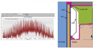
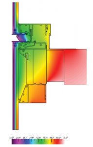
Like spandrel glass, a shadow box will generally block solar heat from passing through the assembly and into the building. Because the glass is transparent solar heat will build up in the cavity behind the glass, however. The amount of solar heat buildup will depend on the construction details (e.g. IGU or non-insulating glass, low-e coating type, vented or unvented cavity, color of metal panel, insulation thickness) and project-specific climate (e.g. building location, solar orientation) and needs to be carefully considered by the designer.
Typically, project-specific finite element analysis (FEA) is required to accurately calculate heat buildup within the cavity (Figure 4). Excessive solar heat buildup within the cavity can be problematic. It can result in a variety of issues such as glass bowing and/or breakage, buckling (oil-canning) of metal panels, and off-gassing and degradation of materials, amongst other adverse effects. As a result, glass in shadow box assemblies is often heat-treated (to reduce risks of glass breakage), metal panels are often solid metal plate panels (i.e. not composite metal panels, which can lead to off-gassing), attachment of the intermediate panel to perimeter framing is designed to allow for thermal expansion/contraction, and the air cavity can be vented.
 [7]
[7]Illustration courtesy Simpson, Gumpertz & Heger and Oldcastle Building Envelope
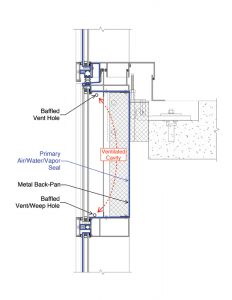
If the shadow box is vented, it is typically vented to the exterior. This is advantageous in the winter in cold climates when the outside air is cold and dry which helps to dehumidify the shadow box cavity. On the other hand, venting the cavity to the interior would likely result in the introduction of moisture from the building interior causing condensation within the assembly during cold winter weather (e.g. evening, night, or morning during cold exterior temperatures).
When vented to the exterior, the primary air-water-vapor seal of the system must be provided by either the intermediate metal panel or the metal back-pan. This metal panel must be fully sealed to the perimeter framing, including sealing the framing joinery (e.g. vertical-to-horizontal mullion interface) and all fastener penetrations through the metal panel (Figure 5). When vented to the exterior, this metal panel must also be designed to accommodate wind loads. Note, when venting to the exterior, a foil-facer on the thermal insulation (which is typically only taped to the perimeter framing from the interior) will unlikely have adequate structural capacity to resist applied wind loads and should not be designed to function as the primary air and water barrier. Therefore, with a vented design, the metal panel (either intermediate panel or the metal back-pan) must be sealed.
 [8]
[8]Illustration courtesy Simpson, Gumpertz & Heger
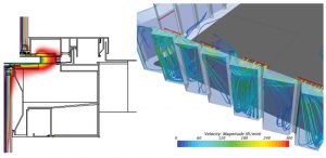
Condensation risks at shadow boxes are like those described previously for spandrel glass and often require FEA analysis (in some cases computational fluid dynamics [CFD] modeling) to assess risks (Figure 6). Because shadow boxes are transparent/translucent, unlike spandrel glass, if condensation forms it can be readily visible from the exterior. If the assembly is vented to the exterior, the condensation may eventually dissipate (as described in the example at the introduction of this article). Prolonged periods of high exterior humidity can lead to a perception of a problem notwithstanding a possible visual objection. Use of IGUs compared to monolithic/laminated glass often tends to provide additional condensation mitigation during fast-changing exterior temperature conditions (e.g. like early morning dew formation in the summer, when the exterior temperature drops at night or morning before the sun has a chance to warm exterior surfaces).
 [9]
[9]Illustration courtesy Simpson, Gumpertz & Heger and Oldcastle Building Envelope
In addition to condensation risks, if the venting is not properly designed and/or constructed, dust/debris from the outside environment can enter the cavity. Should this occur, it can result in the appearance of a film on the glass which may also lead to streaking from condensation. If dust/debris or streaking occurs, it is generally considered trapped as the interior surfaces of the shadow box are inaccessible. To clean the surfaces, the glass would need to be deglazed (from the exterior), cleaned, and reinstalled. This procedure presents its own challenges as reglazing requires the skill of a glazing subcontractor and carries the costs associated with glass replacement (and if the glass is structural silicone-glazed, additional technical challenges of reglazing structural silicone in the field). Further, access equipment may be perceived as an unacceptable maintenance exercise.
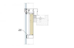
Touch-mullion shadow box
A touch-mullion shadow box is constructed and functions like a traditional shadow box. However, instead of providing a separate piece of glass at the shadow box, the adjacent vision glass panel extends into the spandrel zone, resulting in a single-vision glass panel (Figure 7). A mullion is typically provided to separate the vision zone from the spandrel zone which is often sealed to the inside of the glass with structural silicone. This assembly allows for an even greater seamless visual transition as there is no longer an exterior split between vision and spandrel zones.
 [10]
[10]Illustration courtesy Simpson, Gumpertz & Heger and Oldcastle Building Envelope
Although the glass panel is required to be larger in a touch-mullion (compared to two smaller panels in a traditional shadow box), depending on the aspect ratio, the touch-mullion can provide additional structural support to the glass (e.g. under wind loads). The structural design of the glass, structural silicone, and touch-mullion need to be carefully considered with this type of shadow box.
Heat buildup in the cavity, condensation risks, and consequences of dust/debris/condensation marking the glass are similar in a touch-mullion shadow box. However, as the assembly uses a single glass panel additional challenges must be considered. For instance, a greater thermal stress gradient can occur within the glass panel (requiring heat-treated glass) and must designed accordingly. Further, the seal of the structural silicone at the touch mullion must be to the primary seal of the glass at the vertical mullions to prevent interior humidity (e.g. during cold winter months) from entering the cavity and potentially condensing within the shadow box. Should dust/debris and/or condensation/streaking happen or if glass breakage occurs, the entire glass panel must be deglazed to access for cleaning/replacement. In addition to the field reglazing challenges previously discussed, reglazing the entire glass lite is required at a touch-mullion, resulting in even greater complication such as requiring fall protection and a temporary weather enclosure—both of which can be disruptive to building occupants.
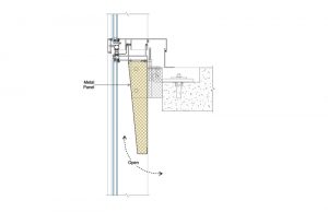
Open shadow box
An open shadow box (sometimes referred to as a ‘faux shadow box’), takes the design one step further by simply eliminating the touch-mullion and allowing the cavity behind the glass to be open to the building interior (Figure 8). A metal closure panel is often installed as part of the glazing system to visually conceal the slab edge and ceiling plenum behind.
As the structural support of a touch-mullion no longer exists, the span of the glass panel is greater and, therefore, may need to be thicker compared to other glass spandrel types.
Risks of heat buildup within the cavity, glass differential thermal stress, and risks of condensation are greatly diminished with the open shadow box as the cavity is fully open to the building interior. This also allows more natural daylight into the space, while at the same time introduces more solar heat gain into the building (which may be beneficial in colder climates). The additional solar heat gain will need to be managed by the building’s mechanical system.
Depending on a variety of factors (e.g. depth/height/geometry of the cavity, color of metal panel, and thickness of insulation), the building’s mechanical system (e.g. diffuser location relative to the open shadow box cavity), presence of interior blinds (e.g. in the down position can preclude beneficial heat resulting in increased risk of condensation in the open cavity; it can also trap solar heat in the cavity) and exterior climate/solar orientation, heat and condensation can still buildup in the cavity.
Generally, with this design, the interior surface of the glass can be more readily accessed from the building interior for maintenance and cleaning activities, if the cavity dimension/geometry are adequate for access. In addition to access for routine cleaning, cavity dimension/geometry must be carefully considered for interior access (e.g. to remove and reinstall structural silicone) for glass replacement.
Other considerations
 [11]
[11]Illustration courtesy Simpson, Gumpertz & Heger and Oldcastle Building Envelope
In addition to the considerations of the various glass spandrel assemblies discussed, additional design and construction considerations include thermal performance, edge-of-slab fire safing, glazing system selection, and construction methodology.
In hot climates solar heat gain (or lack thereof) through glass spandrels (e.g. opaque spandrel glass versus open shadow box) can have a greater influence on overall building energy performance compared to spandrel thermal performance (i.e. U-factor), whereas in cold climates, the reverse can be the case.
The U-factor of glass spandrels can vary depending on the details of the spandrel assembly construction. The primary influences which affect the spandrel system’s thermal performance include the overall size of the spandrel (larger spandrels with less framing generally improve thermal performance), the glass type (i.e. IGU versus non-insulating), insulation thickness, details of the interior membrane/back-pan (i.e. foil-facer versus metal back-pan, including back-pan anchorage details/thermal breaks to the perimeter framing), and the types of thermal break (if any) in the mullion framing (Figure 9). Determination of U-factor performance of spandrel assemblies are calculated as an area-weighted average of system components (typically in general accordance with National Fenestration Rating Council [NFRC] 100, Procedure for Determining Fenestration Product U-factors). Due to the unique nature of glass spandrel assemblies (compared to vision glass), determination of spandrel U-factors can be challenging for some design teams as many of the codes and standards have several shortcomings, and can often result in inaccurate (and often unconservative) calculations.1
 [12]
[12]Illustration courtesy Specified Technologies Inc.
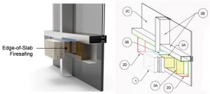
Another important design consideration for spandrel assemblies which extend past the slab edge (e.g. continuous curtain wall systems) include accommodation for fire safing the gap between the edge of the slab and the back of the curtain wall system (Figure 10). Installing a tested joint fire safing system (e.g. in accordance with ASTM E2307, Standard Test Method for Determining Fire Resistance of Perimeter Fire Barriers Using Intermediate-scale, Multistory Test Apparatus) is required to prevent the passage of smoke and flames from one floor to the next.
Fire safing systems typically include filling the gap with mineral wool insulation and covering the top with a smoke seal; fire safing systems can also include additional components like sheet metal depending on the design. In addition to the fire safing system, the performance of the system is also dependent on the details of the construction of the curtain wall’s spandrel assembly. This includes items such as the height of the spandrel, details of the interior membrane/metal back-pan (e.g. metal gauge, stiffeners, anchorage), and insulation type and thickness within the spandrel assembly. Often, engineering judgements based on tested assemblies (or project-specific testing) are required to demonstrate code compliance of unique glass spandrel assemblies.
Perhaps one of the most important considerations in glass spandrel design is the method of construction. In general, factory-glazed spandrel assemblies—unitized curtain wall or window wall—are preferred over field-assembled systems, such as stick-built curtain wall thanks to improved quality control and the ambient environment offered by factory conditions. This is particularly true for vented shadow box assemblies which use a metal back-pan that functions as the system’s primary air-water-vapor seal. Mullion frame joinery is typically sealed in unitized systems and, therefore, the primary air-water-vapor seal can be accommodated in various locations throughout the depth of the mullion, whereas with stick-built, the primary air-water-vapor seal is at the shoulder of the mullion. For these reasons, venting is common in unitized systems as it can easily be accommodated in the design. On the other hand, integrating venting into stick-built curtain walls can be more of a challenge as the system’s air-water-vapor seal design does not necessarily easily accommodate venting.
Further, proper installation of critical air-water-vapor seals in the field can be particularly challenging where access for installation is often limited at the slab edge. Field-glazing of spandrel assemblies can potentially trap moisture (e.g. on a warm humid day or a rainy day) and/or dust/debris (e.g. due to adjacent construction activities) within the assembly when glazing occurs. If the spandrel assemblies rely on foil-faced insulation as the interior vapor seal for preventing condensation, transportation, and installation, adjacent construction activities can easily damage the often-delicate foil-facers. This alone is often a good reason for using more robust metal back-pans instead. In addition, actively humidified buildings (e.g. museums, hospitals) in cold climates, present increased risks of wintertime condensation in the shadow box cavity (as well as on the interior surface of the vision glass). In these cases, well-sealed, thermally broken, robust metal back-pans in lieu of taped-foil facers are often required.
For factory-glazed assemblies, surfaces within the shadow box assemblies (e.g. interior surface of glass, metal panels) must be properly cleaned prior to glazing. In addition, exposed baffled vent/weep holes of bunked unitized panels must be properly protected during storage, transportation, and prior to installation on-site to prevent potential dust/debris and moisture (and potentially bulk water) from entering the cavity.
Recommendations and conclusions
There are a variety of important design and construction considerations when integrating glass spandrels into building façades. A variety of documents have been published on glass spandrels over the years within the industry; at the time of this article’s publication, FGIA and AAMA are in the process of publishing a new technical document titled “Spandrel and Shadow Box Design Considerations.” Although much of the technical design of glass spandrels can be analyzed and calculated, thoughtful judgement is required based on the results of analyses, empirical testing, real-world experience, careful consideration, balancing, as well as prioritization of project-specific requirements.
Industry guidance, architects, engineers, consultants, manufacturers, contractors, and even building owners, often have varied recommendations and opinions for glass spandrel design based on their collective and individual experiences. For example, some insist on vented shadow boxes, others insist on sealed shadow boxes, while others recognize the decision ‘to vent or not to vent’ depends on the project-specific conditions. Some wonder why they should spend extra money on metal back-pans whereas others may never use foil-faced insulation again. The final detailed technical design of a glazing system, including the glass spandrel, is typically delegated to the glazing system subcontractor. It is their responsibility for the system’s design and performance. However, early collaborative discussions should be had amongst all parties, including the owner, architect, consultants, and the various manufacturers and contractors, to help set appropriate expectations and ensure project success.
To vent or not to vent
The decision ‘to vent or not to vent’ glass spandrel assemblies depend on a variety of factors. Both options carry their own advantages and disadvantages as summarized below:
| Vented | |||
| Advantages | Disadvantages | ||
| ● Ventilation allows air pressure relief of solar heat buildup, reducing cavity temperatures and reducing potential for glass and/or metal panel bowing, reducing potential of material off-gassing, and reducing differential glass thermal stress. | ● Dust/debris and condensation/streaking are visible in transparent/translucent glass (shadow boxes). | ||
| ● Ventilation allows cavity condensation to evaporate/dissipate in-service. | ● Ventilation requires the additional cost (if not already included in the design) of a sealed metal panel (intermediate or back-pan). | ||
| ● A ventilated design accommodates realities of construction imperfection (which will allow some air leakage through the system), providing a means to dissipate potential moisture. | ● Incorporating vents and additional seals into the air-water-vapor design of field-glazed systems (e.g., stick-built curtain wall) presents additional challenges. | ||
| Non-vented | |||
| Advantages | Disadvantages | ||
| ● Fully sealing the assembly prevents dust/debris and other contaminants from the outside environment from entering the cavity in-service. | ● Sealed design does not allow for air pressure relief due to solar heat buildup, increases cavity temperatures, increases potential for glass and/or metal panel bowing, increases potential of material off-gassing, and increases differential glass thermal stress. | ||
| ● Does not necessarily require a sealed metal panel (intermediate or back-pan) and foil-faced insulation (often more cost-effective, albeit with other durability concerns) can be used instead. | ● Properly designed and constructed ventilation allows cavity condensation to evaporate/dissipate in-service. | ||
| ● Sealed designs can be incorporated into both factory-glazed (e.g., unitized curtain wall) and field-glazed (e.g., stick-built curtain wall) systems. | ● A perfectly, fully sealed design is not realistic; realities of construction imperfection will allow some air leakage through the system, creating potential risks for trapping moisture (without a designed means to dissipate) and trapping dust/debris within the cavity. | ||
![]() [13]John Jackson is a senior project manager with Simpson Gumpertz & Heger’s Building Technology group in Washington, DC. His work focuses on the design and engineering of innovative enclosure systems, with particular expertise in curtain walls, custom glazing systems, structural glass, and glass investigations. Jackson can be reached at jajackson@sgh.com[14].
[13]John Jackson is a senior project manager with Simpson Gumpertz & Heger’s Building Technology group in Washington, DC. His work focuses on the design and engineering of innovative enclosure systems, with particular expertise in curtain walls, custom glazing systems, structural glass, and glass investigations. Jackson can be reached at jajackson@sgh.com[14].
- [Image]: https://www.constructionspecifier.com/wp-content/uploads/2021/08/Glass_Spandrels_Inset.jpg
- [Image]: https://www.constructionspecifier.com/wp-content/uploads/2021/08/intro_right.jpg
- [Image]: https://www.constructionspecifier.com/wp-content/uploads/2021/08/Figure-1_Moses.jpg
- [Image]: https://www.constructionspecifier.com/wp-content/uploads/2021/08/Figure-2_Moses.jpg
- [Image]: https://www.constructionspecifier.com/wp-content/uploads/2021/08/Figure-3_Moses.jpg
- [Image]: https://www.constructionspecifier.com/wp-content/uploads/2021/08/Figure-4_Moses.jpg
- [Image]: https://www.constructionspecifier.com/wp-content/uploads/2021/08/Figure-5_Moses.jpg
- [Image]: https://www.constructionspecifier.com/wp-content/uploads/2021/08/Figure-6_Moses.jpg
- [Image]: https://www.constructionspecifier.com/wp-content/uploads/2021/08/Figure-7_Moses.jpg
- [Image]: https://www.constructionspecifier.com/wp-content/uploads/2021/08/Figure-8_Moses.jpg
- [Image]: https://www.constructionspecifier.com/wp-content/uploads/2021/08/Figure-9_Moses.jpg
- [Image]: https://www.constructionspecifier.com/wp-content/uploads/2021/08/Figure-10_Moses.jpg
- [Image]: https://www.constructionspecifier.com/wp-content/uploads/2021/08/Jackson_Headshot.jpg
- jajackson@sgh.com: mailto:jajackson@sgh.com
Source URL: https://www.constructionspecifier.com/glass-spandrels-and-shadow-boxes-design-and-construction-considerations/