

Challenges
The large scale of the ceiling, compounded by the complications of working within the confines of the existing structure, presented significant engineering challenges. The intricacy of its design only elevated the difficulty.
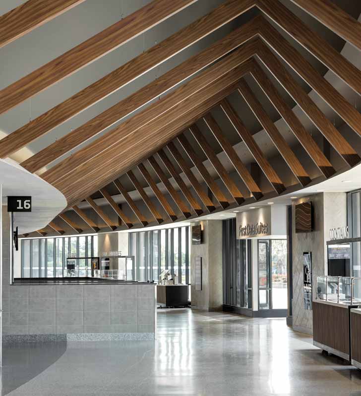
The ceiling comprises approximately 1828 m (6000 ft) of custom-engineered elements: 200 rafters set 1.8 m (6 ft) apart at 24 unique angles, mounted with 1200 brackets. Each rafter is created from two beams of varying sizes. The longer of the two ranges in size from approximately 3.8 to 4.7 m (12 ½ to 15 ½ ft), while the shorter falls between 1.2 and 2.9 m (4 and 9 ½ ft). They meet at angles ranging from 132 to 157 degrees.
Suspending the beams from the existing plenum and soffits forced the engineering team to reckon with complicated angles—and lots of them.
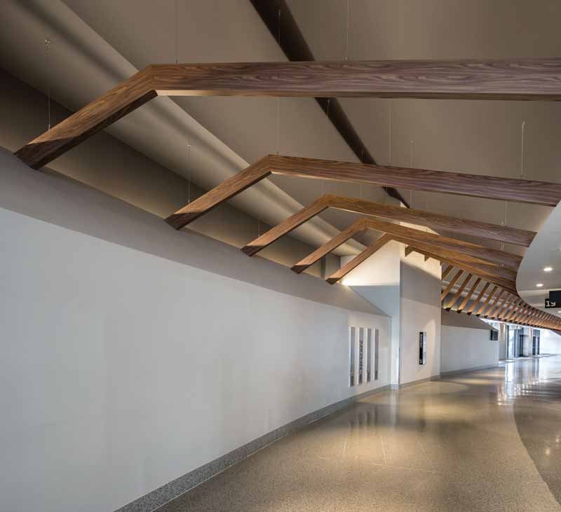
“Overall, the biggest challenges were involved in the engineering of the angles, lengths of beams, and weight that was attached to the ceiling or resting on the bulkhead,” said Pope. “Having 20 to 30 angles means you have 40 to 50 unique cuts to make.”
The plenum slopes upward from the outer edge, while the soffits on each side of the corridor slope downward. With the coliseum’s ovular layout, those angles run perpendicular to the long curvature of the structure’s perimeter. This meant an abundance of custom cuts were required to ensure each beam fit flush against one soffit and within a tolerance of 0.8 mm (31.4 mils) for the center joint. To mitigate this, the project team selected a product made of extruded aluminum, a highly durable material allowing for precise angle cuts.
There were also suspension challenges. To ensure fire resistance, the design called for minimal penetrations through the fire barrier to the structure—only four or five penetrations per beam. To prevent the rafters from physically swaying back and forth on the aircraft cable (the perceived movement lies in the construction alone) the design team specified alignment brackets to attach the beams on either side at the soffits.

