Holding it All Together: Designing, specifying, and installing connectors

General instructions for the designer
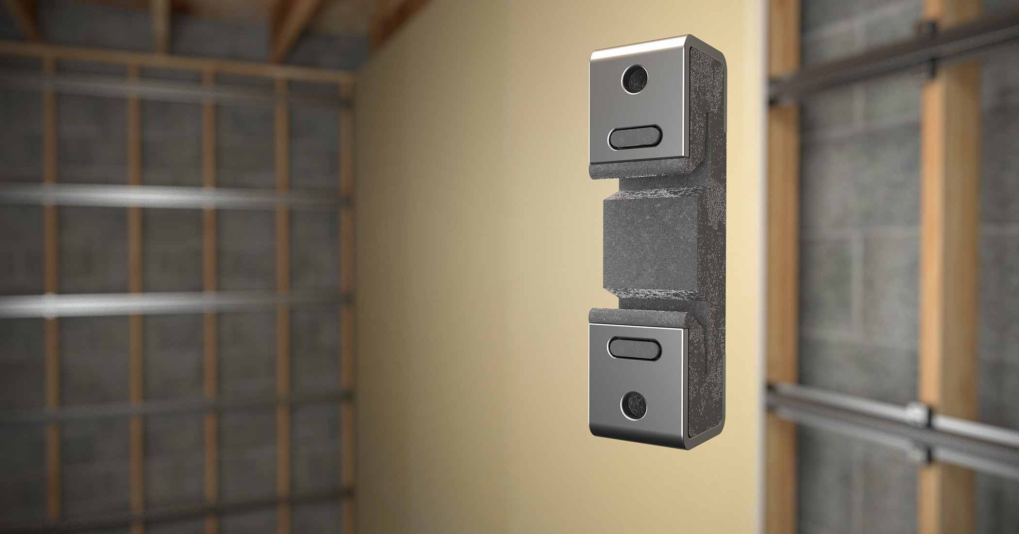
To ensure proper selection and installation of
pre-engineered/premanufactured connector products, design professionals should follow
certain general instructions. The recommendations in the following section are in addition to the specific design and installation instructions and notes provided for each particular product, all of which should be consulted before and during the design process.
1. The term ‘designer’ is intended to mean a licensed/certified building design professional, a licensed professional engineer, or a licensed architect.
2. Allowable loads are determined per American Iron and Steel Institute (AISI) S100, North American Specification for the Design of Cold-formed Steel Structural Members, unless otherwise specified. Other code agencies may use different methodologies of their own.
3. The allowable load is typically limited to an average test load at 3-mm (1/8-in.) deflection, or an average or lowest test value (nominal load) divided by a safety factor or the calculation value. The safety factor is prescribed by Section F1 of AISI S100.
4. Allowable simultaneous loads in more than one direction on a single connector must be evaluated as follows:
Design Uplift/Allowable Uplift + Design Lateral Parallel to Track/ Allowable Lateral Parallel to Track + Design Lateral Perpendicular to Track/Allowable Lateral Perpendicular to Track ≤ 1.0
The three terms in the unity equation are due to the three possible directions to generate force on a connector. The number of terms that must be considered for simultaneous loading is at the sole discretion of the designer; it depends on his or her method of calculating wind forces and the utilization of the connector within the structural system.
5. All connected members and related elements shall be designed by the designer.
6. Unless otherwise noted, member strength is not considered in the loads given and, therefore, one should reduce allowable loads when member strength is limiting.
7. The average ultimate breaking strength for some models is listed under ‘nominal tension load.’
8. The dimensions of the supporting member must be verified as sufficient to receive the specified fasteners, and develop the top flange bearing length.
9. Most of the allowable loads provided by manufacturers of pre-engineered, premanufactured connectors are based on the traditional allowable stress design (ASD) methodology. A method for using load and resistance factor design (LRFD) for cold-formed steel is also included in AISI S100. When designing with LRFD, the nominal connector strength multiplied by the resistance factor must be used.
10. All steel-to-steel connector screws must comply with ASTM C1513, Standard Specification for Steel Tapping Screws for Cold-formed Steel Framing Connections.
11. Screw strength shall be calculated in accordance with AISI S100 Section E4 or be based on the manufacturer’s design capacity, which is determined from testing.
12. Local and/or regional building codes may demand meeting special conditions. Building codes often require special inspection of anchors installed in concrete and masonry. To achieve compliance with these requirements, it is necessary to contact the local and/or regional building authority. Except where mandated by code, some pre-engineered, premanufactured products do not require special inspection.
13. When connectors are attached to two cold-formed steel members of different thicknesses, the designer shall use the thinner of the two members for selecting allowable loads.
Sign up for our weekly newsletter
Architectural materials and methods delivered right to your inbox
- CSI News and Notes: CSI Foundation’s construction camp; CSI spring exam; and more
- CSI News and Notes: CSI’s credentials; CSI conference theme; and more
- To be specific – CSI supports young AECO professionals
- CSI News and Notes: CSI’s foundation scholarships, national conference, and Crosswalk
- CSI News and Notes: AI’s impact; CSI 2024 conference, and more
Products


Read the Latest Issue