Roofing assemblies create varying degrees of barriers between areas of differing vapor pressures. Therefore, if a roof is insufficiently insulated, warm, moist air will rise into the assembly above, where it can cool to its dew point temperature, creating the necessary conditions for condensation to occur. The rate at which the air cools depends on the R-value of the material it is passing through, with the choice and thickness of insulation having the greatest impact.
Vapor drive from interior to exterior is likely to be strongest when the exterior temperature and RH are low and the interior temperature and RH are high. These conditions occur most often during winter months in cooler regions, as warmer interior air exerts a higher vapor pressure than cooler air outside.
The primary goal of the method explored in this article is to establish the conditions at the warm side of the vapor retarder (i.e. the underside), where it must remain warmer than the dew point temperature of the entire roof assembly. This article uses as its central example an assembly including an above-deck rigid polyisocyanurate (polyiso) insulation board—a material chosen because of its high thermal resistance or R-value (per inch of thickness).
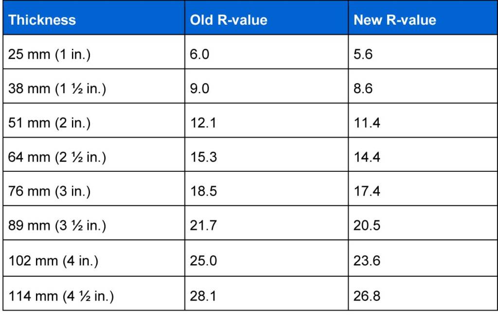
Additionally, for this article, this author calculates the dew point temperatures using the recently updated long-term thermal resistance values (LTTR). These R-values, which are based on ASTM C1289-11A, Standard Specification for Faced Rigid Cellular Polyisocyanurate Thermal Insulation Board, became effective on January 1, 2014. LTTR values predict product R-value after five years, which is equivalent to a time-weighted thermal design R-value for 15 years (Figure 2).
A practical example
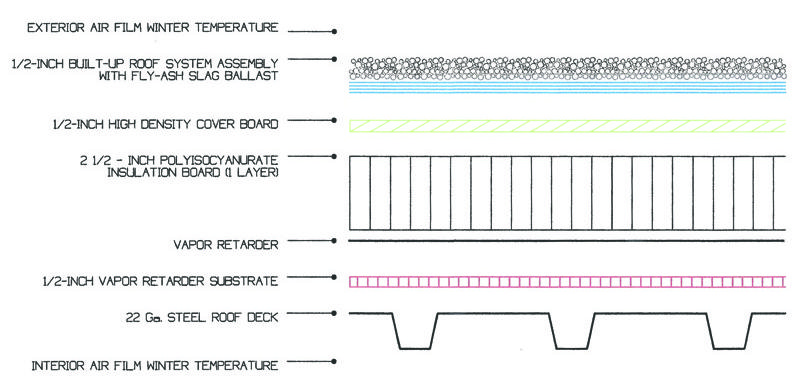
The first step in this process is to create a list of the components being evaluated. In this article’s example, there are eight individual components comprising the roof assembly necessary to develop an accurate R-value profile:
- exterior air film;
- five-ply BUR roof system with a covering of embedded fly-ash slag ballast;
- 12-mm (½-in.) thick high-density (HD) insulation coverboard;
- 64-mm (2 ½-in.) thick layer of rigid polyiso insulation board;
- three-ply BUR vapor retarder;
- compatible HD vapor retarder substrate;
- 22-gauge (Type B) steel roof deck; and
- interior air film.
(For an expanded illustration of the individual components, see Figure 3.)

Images courtesy Anthony Katona
The actual BUR portion of this article’s roof system consists of one ply of asphalt-coated, fiberglass base-sheet type #30, and four plies of Type IV fiberglass asphalt interply felt. The vapor retarder is similar—one ply of the former and two plies of the latter. Each ply is set into a full mopping of Type IV hot asphalt.
Each component of these manufactured goods meets its respective ASTM standard:
- ASTM D4601, Standard Specification for Asphalt-coated Glass Fiber Base Sheet Used in Roofing;
- ASTM D2178, Standard Specification for Asphalt Glass Felt Used in Roofing and Waterproofing; and
- ASTM D312, Standard Specification for Asphalt Used in Roofing.
The composition of the roofcovering in this example consists of a gravel surfacing of fly-ash slag ballast meeting ASTM C1289. The slag has been broadcast and embedded into a complete flood coat of Type IV hot asphalt meeting ASTM D312.
Determining dew point requires selecting a specific geographical location with a known value of the exterior design dry-bulb temperature (i.e. temperature of air as measured by an ordinary thermometer) for winter, as this is when the warm air is most likely to be rising through the roof assembly. This data can be found in Appendix 3 (“Climate/Design Data”) of NRCA’s Roofing and Waterproofing Manual, fifth edition. This article’s hypothetical example is located in Allentown, Pennsylvania—selected because this geographic local meets the design criteria used throughout the article.


Why is there a vapor retarder placed on top of the metal deck?
Metal is vapor tight (μ-value = infinite), which makes is a perfect vapor barrier. Seams in the metal deck can be taped, but so do the seams in the vapor retarder.