Performing the calculations
Having a working knowledge of all the materials covered thus far in this article, one can now begin the actual steps to perform the calculations, plot the coordinates, and then determine the dew point temperature.
Step 1: Determine the winter (interior) design dry-bulb temperature
This value should come from the HVAC system designer or, for an existing building, either a knowledgeable maintenance engineer or the person maintaining the HVAC and mechanical control systems. For this example, the winter (interior) design dry-bulb temperature is 22.88 C (75 F).
Step 2: Determine the winter (exterior) design dry-bulb temperature
This design value can be found in Appendix 3 (“Climate/Design Data”) of NRCA’s Roofing and Waterproofing Manual (fifth edition) or in Chapter 27 (“Climatic Design Information”) of the 2001 ASHRAE Handbook–Fundamentals. For Allentown, Pennsylvania, the winter (exterior) design dry-bulb temperature is −15.5 C (4 F).
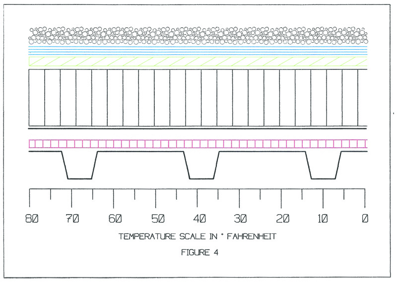
Step 3: Illustrate the roof assembly and plot all individual R-values using the temperature scale beneath the diagram
The starting temperature on the left side of the scale will be the winter interior dry-bulb design temperature. The scale will end on the right side with the winter exterior dry-bulb temperature value. Then, evenly spaced vertical lines are inserted to represent five- and 10-degree increments on the temperature scale (Figure 5).
Step 4: Calculate the heat loss occurring at each material
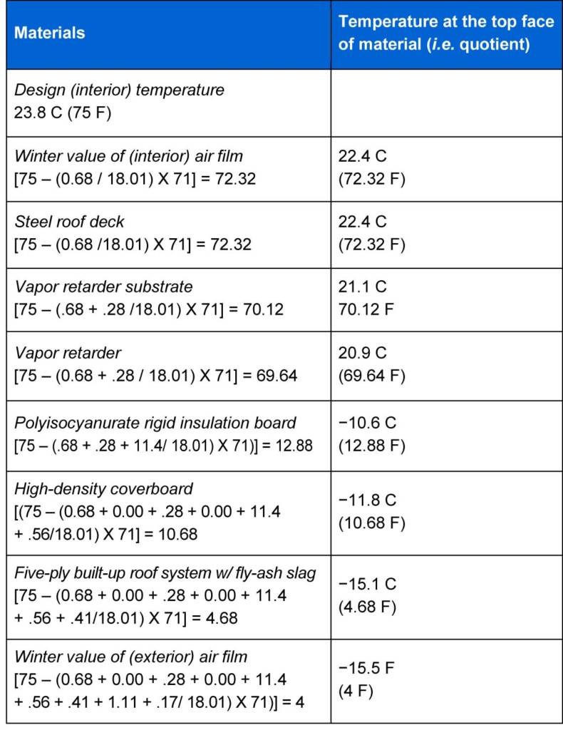
As shown in Figure 6, this step is accomplished using the fundamental heat-loss formula:
Temperature drop = Ti – [(R/Rt) x ΔT]
Where:
Ti = design interior temperature (in Fahrenheit);
ΔT = (winter interior design dry-bulb temp [75]) – (winter exterior design dry-bulb temp [4]) = 71;
R = cumulative R-values of materials starting from the interior air film; and
Rt = total R-value of the entire roof assembly, which was previously determined to be 18.01.
Step 5: Perform the mathematical equations
The next step is to begin the process of carrying out the actual mathematical equations, starting with the interior air film as the first calculation.

1. Interior air film R-value: .68
[75 – (.68 / 18.01) x 71]
75 – (.037 x 71)
75 – 2.68 = 72.32 F
2. Metal deck R-value: .00
[75 – ([.68 + .00 / 18.01] x 71)]
75 – (.037 x 71)
75 – 2.68 = 72.32 F
3. Vapor retarder substrate R-value: .56
[75 – ([.68 + .00 + .56 / 18.01] x 71)]
75 – (0.68 x 71)
75 – 4.88 = 70.12 F
4. Vapor retarder R-value: .12
[75 – ([.68 + .00 + .56 + .12 / 18.01] x 71)]
75 – (.075 x 71)
75 – 5.36 = 69.64 F
5. Polyiso insulation board R-value: 14.4
[75 – ([.68 + .00 + .56 + .12 + 14.4/ 18.01] x 71)]
75 – (.875 x 71)
75 – 62.12 = 12.88 F
6. High-density coverboard R-value: .56
[75 – ([.68 + 0.00 + .56 + .12 + 14.4 + .56/18.01] x 71)]
75 – (0.906 x 71)
75 – 64.32 = 10.68 F
7. Multi-ply BUR with fly-ash slag ballast R-value: 1.52
[75 – ([0.68 + 0.00 + .56 + .12 + 14.4 + .56 + 1.52/18.01] x 71)]
75 − (.990 x 71)
75 – 70.32 = 4.68 F
8. Exterior air film R-value: .17
[75 – ([0.68 + 0.00 + .56 + .12 + 14.4 + .56 + 1.52
+ .17/ 18.01] x 71)]
75 – (1.00 x 71)
75 – 71 = 4 F


Why is there a vapor retarder placed on top of the metal deck?
Metal is vapor tight (μ-value = infinite), which makes is a perfect vapor barrier. Seams in the metal deck can be taped, but so do the seams in the vapor retarder.