

by Harry Lubitz, CSI, CDT
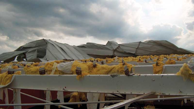
As this article was being written, the country had just gone through one of the most active hurricane seasons on record, with numerous powerful storms making landfall throughout the Gulf Coast, Southeast and Southwest shores, and the Caribbean. Not since 2005 had the United States been hit with a Category 3 or higher storm, but two Category 4 events made landfall in 2017 (Harvey and Irma), while a Category 5 storm (Maria) reached Puerto Rico. The devastating effects of the winds generated by these storms caused considerable damage to structures.
While hurricanes have been a menace since the beginning of recorded history, construction techniques have changed to include improved and more cost effective materials, like metal roofs. Early recorded use of metal roofing dates back millennia, though modern metal roofing use is more of a 19th century story.
Numerous examples of metal roof installations can be traced to the early 1800s in Colonial America and Europe. Corrugated iron roofing was patented in 1829 and became very popular in the mid-1900s primarily due to World War II. These were ‘exposed-fastened’ products, meaning visible exterior fasteners hold the roof in place.
Architectural standing-seam metal roofs (SSMR) were introduced by Kaiser Aluminum in the early 1960s with the first concealed fastened roof produced by Merchant & Evans in 1964. Beginning in the 1970s, standing-seam metal roofs grew rapidly in popularity due to advancements in roll forming and coating technologies providing a multiplicity of seam shapes, spacings, colors, and finishes.
These two types of metal roofs—exposed-fastened and standing-seam (i.e. concealed-fastened)—have different performance characteristics when exposed to high winds.
Images courtesy S-5!
Wind uplift
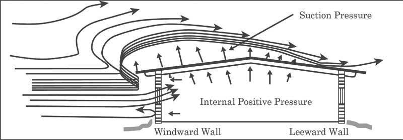
When a gust of wind encounters a structure, by nature it is redirected up the structure’s face and across the top plane of the structure (roof) as it continues its journey. As it is redirected it increases its velocity and creates uplift. Similar to the principles of lift used in aviation, a negative suction pressure is created as the wind passes over the roof of the structure and results in lift that ‘wants’ to pull the roof structure upward.
Wind design is complicated, but it is important to know wind speed is only a place to begin. A designer needs to design in Pascals (or pounds per square foot), rather than kilometers (or miles) per hour. This conversion is complex, given how wind is fluid and it is redirected. Numerous factors ultimately determine the severity of the suction pressure created by this wind uplift.
If the left wall of the building depicted in Figure 1 is much taller than the picture shows, the suction pressure moves to another part of the roof. If there is a tall building next to the structure, then the suction pressure would be different than the first scenario and move to another part of the roof. The engineer is tasked with examining all variables to calculate the correct wind uplift and determine where and how it will impact the roof.
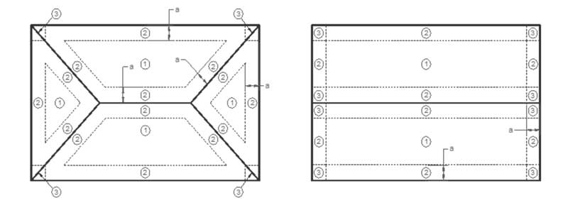
American Society of Civil Engineers (ASCE) 07, Minimum Design Loads for Buildings and Other Structures, is a widely recognized consensus standard method for determining design wind loads on buildings and other structures. It contains provisions for the design of components and cladding (roof systems). Further, it helps determine wind uplift loads for three different zones of a roof system’s area: field, perimeter, and corner. Calculations and equations in ASCE 07 convert wind speed (i.e. mph) to uplift pressure (psf) given job-specific variables.
The 2010 edition is the current consensus standard for calculating wind uplift pressures on a roof. (Last year, ASCE 07-16 was introduced. It is expected this standard will be adopted into building codes over the next several years.) Based on ASCE 07-10, the zones for two different roof types can be seen in Figure 2. The zones are different for different roofs—the pressure requirements will change based on building design and exposure category.

