Building design risk and exposure categories
There are many factors an engineer must consider when calculating wind uplift pressures per ASCE 07-10. One of these concerns is identifying what type of risk to human life the building is protecting, as classified into four categories:
- I—buildings representing low risk to human life in the event of failure—an example would include an agricultural building;
- II—all buildings not covered by the other three categories;
- III—buildings representing substantial hazard to human life, including schools, public assembly spaces, power stations, and water treatment facilities; and
- IV—buildings designated as essential facilities (e.g. emergency services and shelters).
Engineers must also consider where a building is positioned in relation to other structures around it. This will affect the ultimate design wind speed used in their calculation. There are three different Exposure Categories:
- D—buildings located in flat, unobstructed areas not prone to hurricanes;
- C—buildings located in areas with scattered obstructions, generally less than 9.1 m (30 ft) high;
- B—buildings located in urban and suburban areas where structures are closely spaced together.
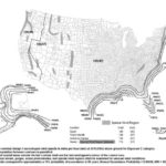
For each of the building design risk categories, the ultimate design wind speeds vary (Figure 3). For example, a Risk Category I building in the central part of the United States would be designed to withstand a three-second wind gust of 170 km/h (105 mph) at 10 m (33 ft) above ground. This applies to an Exposure Category C building.
Other factors engineers consider as part of their calculations include:
- large, open structures or cantilevers (may worsen wind effects);
- parapet walls (may diminish wind effects);
- unusual roof geometries (may worsen or diminish wind effects);
- extreme geometries in adjacent building that disrupt normal wind flows; and
- other unusual aspects, such as tilted photovoltaic (PV) arrays.
The engineer inputs all these variables into their calculations and derives design wind uplift values in PSF for the three different zones of a roof’s area.
Different metal roof types
As mentioned, there are two different metal roof types, and they will perform differently when they are exposed to wind uplift pressures.
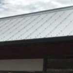
Exposed-fastened (or through-fastened) roofs by definition are rigidly fastened to the structure (Figure 4). The closely spaced fasteners limit this roof type’s ability to change its shape under load. In the photo cited, one can see the fasteners are spaced even closer together on the critical edge zone of the roof to limit the effects of wind uplift. These numerous fasteners, however, can make the roof less attractive and can cause it to develop issues due to the thermal movement of the panel. Consequently, they are most often used in lower-valued agricultural applications or as ‘rustic’ decorative accents often seen on Western-themed restaurants, for example.
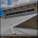
Standing-seam metal roof panels (Figure 5) are attached to a purlin or substrate with clips designed specifically to allow the roof to move, and change dimensionally to accommodate thermal movement. This type of roof panel changes its shape under load and needs to be designed based on specific uplift tests, such as ASTM E1592, Standard Test Method for Structural Performance of Sheet Metal Roof and Siding Systems by Uniform Static Air Pressure Difference, which was developed for this roof type.
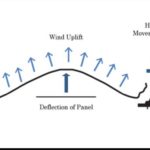
As wind uplift acts on a standing-seam metal roof panel, the suction pressure distorts the panel upward, bowing it in the center (Figure 6). This action can cause a failure in the panel by shifting the seam sideways and splitting the seam. This distorting action could also allow the seam to unhook itself from the mounting hardware. Splitting seams open and unhooking the seams from the mounting hardware are the two most common modes of failure of this type of roof.
Metal roof manufacturers employ several methods to improve a standing-seam metal roof’s performance in the ASTM E1592 test and onsite performance in high wind exposure. Options may include:
- increasing the base gauge of the metal (i.e. make it thicker);
- increasing the number, and decreasing the spacing, of the mounting clips (i.e. add more points of attachment);
- decreasing the panel seam spacing (i.e. reduce the potential deflection area); and
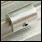
- adding external seam clamps (i.e. reinforce the seam).
All these measures add varying amounts of cost increase to the metal roof. The manufacturer will work with the engineer to provide the best combination of the methods to minimize the cost impact while meeting required design pressures. Of the methods above, the newest innovation is the external seam clamp.


