Improving wind uplift on metal roofs
by Katie Daniel | December 8, 2017 11:24 am
 [1]
[1]by Harry Lubitz, CSI, CDT
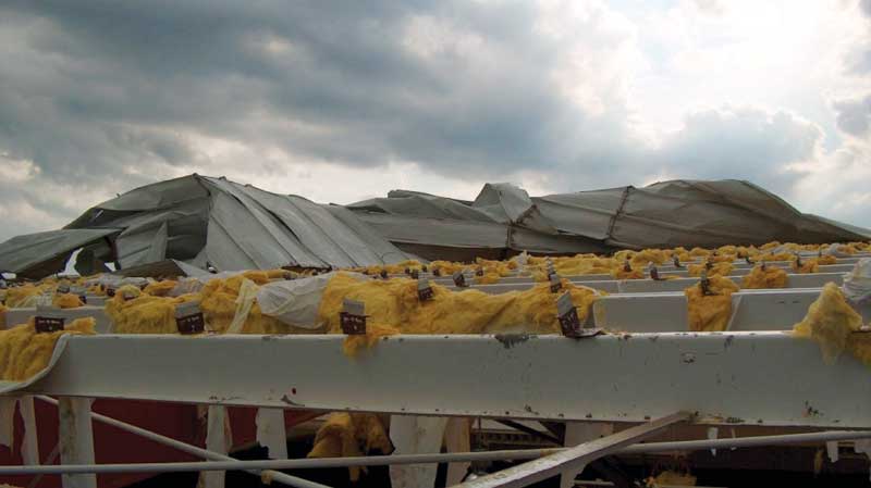
As this article was being written, the country had just gone through one of the most active hurricane seasons on record, with numerous powerful storms making landfall throughout the Gulf Coast, Southeast and Southwest shores, and the Caribbean. Not since 2005 had the United States been hit with a Category 3 or higher storm, but two Category 4 events made landfall in 2017 (Harvey and Irma), while a Category 5 storm (Maria) reached Puerto Rico. The devastating effects of the winds generated by these storms caused considerable damage to structures.
While hurricanes have been a menace since the beginning of recorded history, construction techniques have changed to include improved and more cost effective materials, like metal roofs. Early recorded use of metal roofing dates back millennia, though modern metal roofing use is more of a 19th century story.
Numerous examples of metal roof installations can be traced to the early 1800s in Colonial America and Europe. Corrugated iron roofing was patented in 1829 and became very popular in the mid-1900s primarily due to World War II. These were ‘exposed-fastened’ products, meaning visible exterior fasteners hold the roof in place.
Architectural standing-seam metal roofs (SSMR) were introduced by Kaiser Aluminum in the early 1960s with the first concealed fastened roof produced by Merchant & Evans in 1964. Beginning in the 1970s, standing-seam metal roofs grew rapidly in popularity due to advancements in roll forming and coating technologies providing a multiplicity of seam shapes, spacings, colors, and finishes.
These two types of metal roofs—exposed-fastened and standing-seam (i.e. concealed-fastened)—have different performance characteristics when exposed to high winds.
 [2]
[2]Images courtesy S-5!
Wind uplift
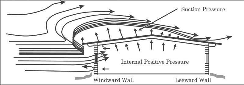
When a gust of wind encounters a structure, by nature it is redirected up the structure’s face and across the top plane of the structure (roof) as it continues its journey. As it is redirected it increases its velocity and creates uplift. Similar to the principles of lift used in aviation, a negative suction pressure is created as the wind passes over the roof of the structure and results in lift that ‘wants’ to pull the roof structure upward.
Wind design is complicated, but it is important to know wind speed is only a place to begin. A designer needs to design in Pascals (or pounds per square foot), rather than kilometers (or miles) per hour. This conversion is complex, given how wind is fluid and it is redirected. Numerous factors ultimately determine the severity of the suction pressure created by this wind uplift.
If the left wall of the building depicted in Figure 1 is much taller than the picture shows, the suction pressure moves to another part of the roof. If there is a tall building next to the structure, then the suction pressure would be different than the first scenario and move to another part of the roof. The engineer is tasked with examining all variables to calculate the correct wind uplift and determine where and how it will impact the roof.
 [3]
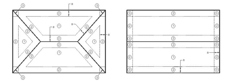
[3]American Society of Civil Engineers (ASCE) 07, Minimum Design Loads for Buildings and Other Structures, is a widely recognized consensus standard method for determining design wind loads on buildings and other structures. It contains provisions for the design of components and cladding (roof systems). Further, it helps determine wind uplift loads for three different zones of a roof system’s area: field, perimeter, and corner. Calculations and equations in ASCE 07 convert wind speed (i.e. mph) to uplift pressure (psf) given job-specific variables.
The 2010 edition is the current consensus standard for calculating wind uplift pressures on a roof. (Last year, ASCE 07-16 was introduced. It is expected this standard will be adopted into building codes over the next several years.) Based on ASCE 07-10, the zones for two different roof types can be seen in Figure 2. The zones are different for different roofs—the pressure requirements will change based on building design and exposure category.
 [4]
[4] [5]
[5] [6]
[6] [7]
[7] [8]
[8]


Building design risk and exposure categories
There are many factors an engineer must consider when calculating wind uplift pressures per ASCE 07-10. One of these concerns is identifying what type of risk to human life the building is protecting, as classified into four categories:
- I—buildings representing low risk to human life in the event of failure—an example would include an agricultural building;
- II—all buildings not covered by the other three categories;
- III—buildings representing substantial hazard to human life, including schools, public assembly spaces, power stations, and water treatment facilities; and
- IV—buildings designated as essential facilities (e.g. emergency services and shelters).
Engineers must also consider where a building is positioned in relation to other structures around it. This will affect the ultimate design wind speed used in their calculation. There are three different Exposure Categories:
- D—buildings located in flat, unobstructed areas not prone to hurricanes;
- C—buildings located in areas with scattered obstructions, generally less than 9.1 m (30 ft) high;
- B—buildings located in urban and suburban areas where structures are closely spaced together.
For each of the building design risk categories, the ultimate design wind speeds vary (Figure 3). For example, a Risk Category I building in the central part of the United States would be designed to withstand a three-second wind gust of 170 km/h (105 mph) at 10 m (33 ft) above ground. This applies to an Exposure Category C building.
Other factors engineers consider as part of their calculations include:
- large, open structures or cantilevers (may worsen wind effects);
- parapet walls (may diminish wind effects);
- unusual roof geometries (may worsen or diminish wind effects);
- extreme geometries in adjacent building that disrupt normal wind flows; and
- other unusual aspects, such as tilted photovoltaic (PV) arrays.
The engineer inputs all these variables into their calculations and derives design wind uplift values in PSF for the three different zones of a roof’s area.
Different metal roof types
As mentioned, there are two different metal roof types, and they will perform differently when they are exposed to wind uplift pressures.
Exposed-fastened (or through-fastened) roofs by definition are rigidly fastened to the structure (Figure 4). The closely spaced fasteners limit this roof type’s ability to change its shape under load. In the photo cited, one can see the fasteners are spaced even closer together on the critical edge zone of the roof to limit the effects of wind uplift. These numerous fasteners, however, can make the roof less attractive and can cause it to develop issues due to the thermal movement of the panel. Consequently, they are most often used in lower-valued agricultural applications or as ‘rustic’ decorative accents often seen on Western-themed restaurants, for example.
Standing-seam metal roof panels (Figure 5) are attached to a purlin or substrate with clips designed specifically to allow the roof to move, and change dimensionally to accommodate thermal movement. This type of roof panel changes its shape under load and needs to be designed based on specific uplift tests, such as ASTM E1592, Standard Test Method for Structural Performance of Sheet Metal Roof and Siding Systems by Uniform Static Air Pressure Difference, which was developed for this roof type.
As wind uplift acts on a standing-seam metal roof panel, the suction pressure distorts the panel upward, bowing it in the center (Figure 6). This action can cause a failure in the panel by shifting the seam sideways and splitting the seam. This distorting action could also allow the seam to unhook itself from the mounting hardware. Splitting seams open and unhooking the seams from the mounting hardware are the two most common modes of failure of this type of roof.
Metal roof manufacturers employ several methods to improve a standing-seam metal roof’s performance in the ASTM E1592 test and onsite performance in high wind exposure. Options may include:
- increasing the base gauge of the metal (i.e. make it thicker);
- increasing the number, and decreasing the spacing, of the mounting clips (i.e. add more points of attachment);
- decreasing the panel seam spacing (i.e. reduce the potential deflection area); and
- adding external seam clamps (i.e. reinforce the seam).
All these measures add varying amounts of cost increase to the metal roof. The manufacturer will work with the engineer to provide the best combination of the methods to minimize the cost impact while meeting required design pressures. Of the methods above, the newest innovation is the external seam clamp.
External seam clamps
Shown in Figure 7, external seam clamps (i.e. wind clamps) are extruded pieces of aluminum placed on the panel seams to prevent male-to-female seam separation. When used at clip locations, these devices also prevent seam-to-clip disengagement.
Wind clamps significantly increase the uplift capacity of the roof panel system. Recent testing by independent laboratories and metal roof manufacturers have shown design load improvements of 50 percent, to as much as 300 percent, using the ASTM E1592 test protocol. With the low cost of these products compared to other mitigation options, metal roof manufacturers are finding the seam clamps to be value-driven solutions to meeting test pressures.
Factory Mutual began studying these clamps several years ago as a cost-effective method to increase design roof pressures for metal roof assemblies. Based on their successes, it began requiring FM-approved external seam clamps on standing-seam metal roofs in areas subject to cyclones and hurricanes, beginning mid-2016.
Specifying external seam clamps is a relatively simple addition to the standing-seam roof panel section. Adding one descriptive paragraph into the metal roof accessories subsection is all that is necessary to increase their overall performance and longevity.
Conclusion
Architectural standing-seam metal roofing can be a long-lasting and attractive solution that provide many years of protection against the elements, including severe tropical storms and hurricanes. Methods and products for designing these roofs to withstand significant wind events include increasing the gauge of the metal and decreasing the seam spacing and adding external seam clamps. This assists in mitigating the negative effects of wind uplift on these roof types, keeping them in place to protect the structure, along with its occupants and contents.
External seam clamps have shown to be a cost-effective method in providing significant wind uplift mitigation. As metal roof manufacturers continue to perform ASTM tests with this new option, they are finding instances when metal roofs could be considered where before they were unable to meet required pressures. They are also finding external seam clamps as a simple and cost-effective method to upgrade existing metal roofs.
To ensure the best options possible are being specified, one should include ASTM E1592 in the specification as the proper test regimen for standing-seam metal roofs. Adding external seam clamps into the Roof Accessories section can also be an important consideration for a project.
| CASE STUDY EXAMPLE |
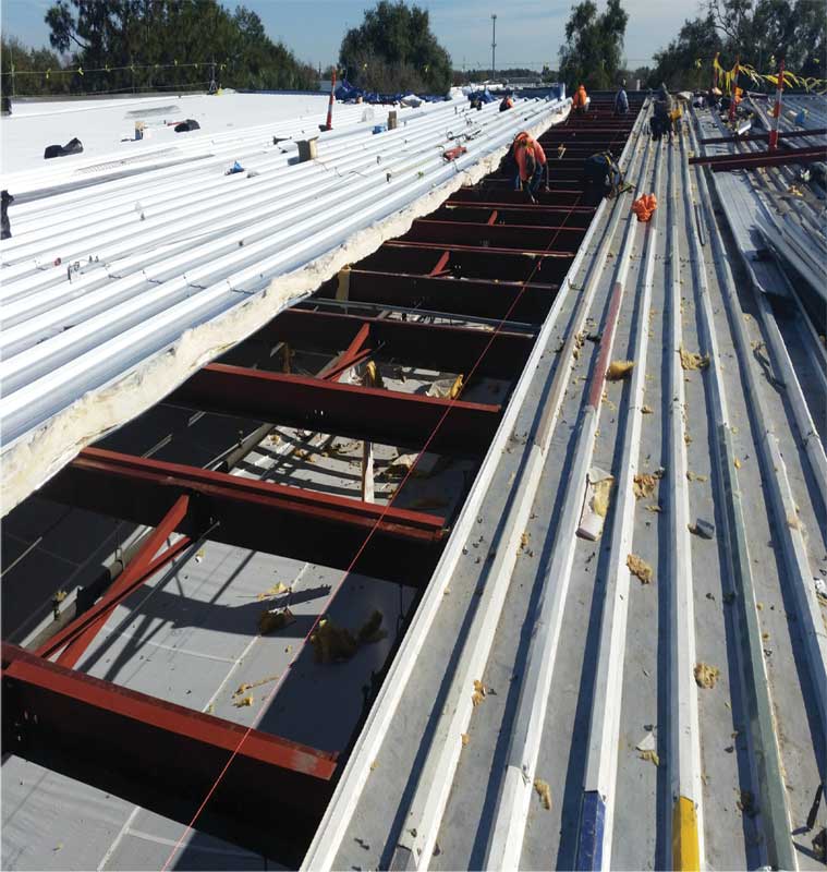 [9] [9]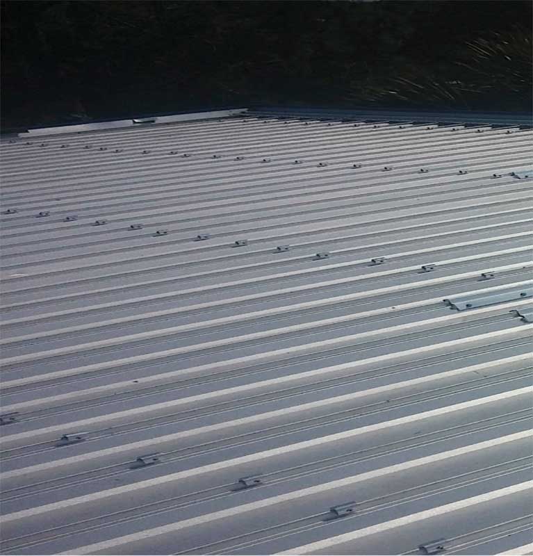 [10] [10]In 2013, the roof of Trulite Glass’ manufacturing facility in Orlando blew off when wind entered open doors during a micro-burst and caused positive internal pressure in the building. The roof is approximately 76 x 76 m (250 ft x 250 ft) and had a projected replacement cost of $1.4 million. Existing roof purlins were 1.5 m (5 ft) on center (o.c.), as shown in Photo A. To bring the roof up to current code standards, purlins would have to be added at 0.76 m (2 ½ ft) o.c., and the roof seams would have to be placed 305 mm The metal roof manufacturer offered an alternate solution to additional purlins/mounting clips and decreased seam spacing based on ASTM E1592, Standard Test Method for Structural Performance of Sheet Metal Roof and Siding Systems by Uniform Static Air Pressure Difference, testing of its product using external seam clamps. By adding these wind clamps, the design permitted purlin spacing to be maintained at 1.5-m centers. It also enabled panel seams to be decreased in the roof center—there was 305-mm spacing on edge zones and 610-mm (24-in.) spacing in the center zone. While these changes saved several thousand dollars in materials and labor, the big savings were felt by the operating facility itself. As there were no purlins added, there was no interior building work required. This allowed the factory to run unimpeded during the entire reroofing process, savings hundreds of thousands of dollars in manufacturing interruptions and shutdowns. All these savings were achieved for the cost of a few thousand dollars on wind clamps added to the project (Photo B). |
Harry J. Lubitz, CSI, CDT, is the architectural and national accounts manager for S-5! Metal Roof Innovations (Colorado Springs, Colorado). He works with the design community to develop and improve architectural specifications for metal roofs and attachment systems. Lubitz has more than 25 years of experience in the building materials industry, is active in numerous architectural and professional organizations including CSI, and has served as an adjunct faculty member at Lord Fairfax Community College in Virginia. He can be reached via e-mail at hlubitz@S-5.com[11]
- [Image]: https://www.constructionspecifier.com/wp-content/uploads/2017/12/Wind-Damage.jpg
- [Image]: https://www.constructionspecifier.com/wp-content/uploads/2017/12/figure1.jpg
- [Image]: https://www.constructionspecifier.com/wp-content/uploads/2017/12/figure2.jpg
- [Image]: https://www.constructionspecifier.com/wp-content/uploads/2017/12/figure3.jpg
- [Image]: https://www.constructionspecifier.com/wp-content/uploads/2017/12/figure4.jpg
- [Image]: https://www.constructionspecifier.com/wp-content/uploads/2017/12/figure5.jpg
- [Image]: https://www.constructionspecifier.com/wp-content/uploads/2017/12/figure6.jpg
- [Image]: https://www.constructionspecifier.com/wp-content/uploads/2017/12/figure7.jpg
- [Image]: https://www.constructionspecifier.com/wp-content/uploads/2017/12/Photo-A.jpg
- [Image]: https://www.constructionspecifier.com/wp-content/uploads/2017/12/Photo-B.jpg
- hlubitz@S-5.com: mailto:hlubitz@S-5.com
Source URL: https://www.constructionspecifier.com/improving-wind-uplift-metal-roofs/