Installing thermoplastic or rubber waterstops
by Erik Missio | June 29, 2015 8:57 am
 [1]
[1]By Stacy Byrd, GRP, LEED AP
In the July 2015 edition of The Construction Specifier, this author examines[2] various aspects of waterstops. In this web feature, issues concerning the installation of dumbbell and ribbed center-bulb models are explored.
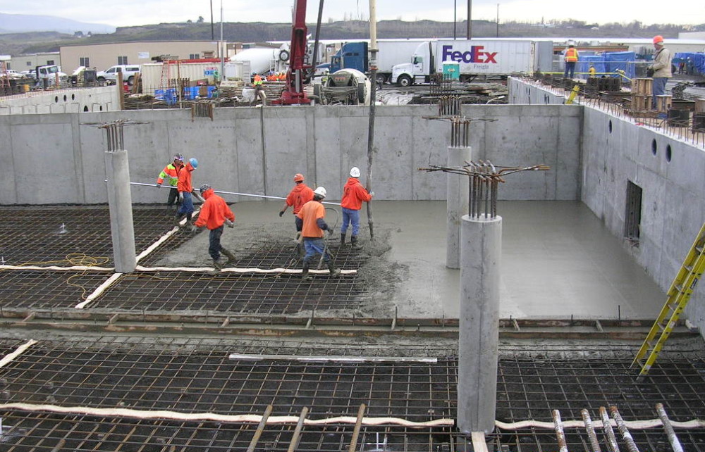
Installation plays a critical part in the performance and effectiveness of a waterstop system—most failures occur because proper steps are not taken. The waterstop should be installed in a layout that forms a continuous watertight diaphragm. Dumbbell and ribbed center-bulb waterstops should be positioned with the longitudinal centerline of the waterstop coincides with the center of the joint. Prior to the first concrete pour, hog rings or grommets are applied to the outermost edges of the waterstop profile (usually at 305-mm [12-in.] intervals) to provide the installer with a convenient means of securing the waterstop to adjacent steel rebars. Tie wire is inserted through the hog rings to attach the waterstop and maintain proper positioning.
Several manufacturers provide guidance to position the waterstop so concrete coverage is not less than half its width. Clearance should be allowed between the waterstop and reinforcing steel of a minimum two times the largest aggregate size to prevent poor consolidation of concrete caused by aggregate bridging. Also, one must adhere to the manufacturer’s guidelines for depth of embedment in the concrete for various head pressures. General rule of thumb—for higher hydrostatic pressures, the waterstop is installed with greater concrete coverage.
Waterstops need splicing at intersections, changes of direction, or to form longer lengths. To form a continuous diaphragm, ends should be cut square before welding together adjacent rolls. Welds should be made by trained personnel using approved equipment and procedures. Uncoil waterstop rolls and lay flat for 24 hours before installation for ease of handling and fabrication.
Heat is applied using a thermostatically controlled electric splicing iron with Teflon-film cover to avoid adhering the waterstop material. After preheating the iron to the temperature recommended for the type of thermoplastic material, the waterstop ends are pressed against the hot iron until the material becomes slightly molten. The splicing iron is removed, and then the molten ends are immediately pressed together and held like this until cool (less than one minute). This heat-splicing method should only be employed with waterstops made of thermoplastic materials. Conventional rubber waterstops are typically cold-spliced using special adhesives.
In vertical joints, split-forming is used to hold the waterstop in position. However, special split-leg profiles can be attached to conventional concrete forms with nails. For all installations, one must ensure the center of the profile is aligned with the center of the joint.
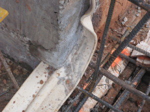
Investigations have shown the majority of waterstop failures are caused by poor welds or that no welding was performed. Splices should be inspected to confirm they are welded through the entire profile thickness and not simply on the surface of one side (i.e. edge welding). One must also look for any charred, burnt, or otherwise-contaminated welds. Further, continuity of the center bulbs and ribs must be maintained as continuous throughout the weld. Edge welding waterstop seriously compromises the integrity of any product. Even limited movement of concrete can rupture edge welded splices because the thin-edge weld lacks proper tensile strength and elongation relative to the parent material.
Experience has shown field-welded mitered fittings are difficult to splice correctly. For this reason, it is recommended directional change fittings (e.g. Ls, Ts, and crosses) be prefabricated by the manufacturer, leaving only simple butt-splicing to be performed in the field. For example, a standard flat cross fitting has 12 cuts and seven welds. By using prefabricated fittings, all the cuts and three of the welds are eliminated from fieldwork.
The most leak-prone area is the directional change fittings. Prefabricated fittings can eliminate or greatly reduce this problem as the waterstop manufacturer has the specialized equipment and templates unavailable to the contractor in the field. Ls, Ts, and crosses are available in both vertical and flat styles.
During installation, one must avoid contaminating the waterstop surface with dirt, oil, or release agents. Surface contamination can interfere with direct contact of concrete with the waterstop, affecting its performance. Concrete must be carefully placed without displacing the waterstop from its position. The waterstop must be held in place properly during the first half of the concrete placement, with one half of the width embedded in the concrete. This must be carefully monitored for quality control to ensure the waterstop remains positioned during both halves of the concrete placement and consolidation. Far too often, the PVC waterstop ends up shifted, folded over, or the center misaligned with the joint, preventing it from functioning properly.
Additionally, with horizontal-run installations, any concrete that has extruded out into the flange must be removed. Finally, there is inspection for any damage that must be prepared—workers installing the reinforcing bars often burn, puncture, or cut the waterstop.
 [3]
[3]Base-seal profiles are suitable for construction, contraction, and expansion joints. Base-seal should not be used to make interior wall transitions as the embedment ribs are only on one side and therefore cannot function correctly.
Base-seal waterstops are installed before placement of the concrete and placed either on compacted grade, mud slabs, or vertical formwork. Base-seal waterstops are positioned such that only the ribbed side of the waterstop engages the concrete. Since the base-seal waterstop is not embedded in the concrete, a solid substrate is required for initial support as well as for proper in service performance. Lack of support can lead to edge curling of the waterstop when exposed to high hydrostatic pressure.
Care should be taken in the placement of concrete to prevent movement or displacement of the waterstop. Center-bulb tear-web varieties of base-seal can accommodate joint movements. For high hydrostatic head pressures, manufacturers recommend ribbed center-bulb embedded in the concrete instead of base-seal products.
Finally, one must always wear protective gear including, but not limited to, temperature-resistant gloves, safety eyewear, protective shoes, and a respirator in confined spaces. Welding should be done in a well-ventilated area.
 [4]Stacy Byrd, GRP, LEED AP, is the national products manager at CETCO, a manufacturer of waterproofing, green roof systems, composite drainage, and waterstops. He has a quarter-century of technical waterproofing design application and practical field experience with below-grade foundations, plaza-decks, tunnels, and vegetated roofs on commercial, institutional, civic, and government projects. Byrd is an active member with ASTM International Committee D08 on Roofing and Waterproofing and a Green Roof Professional (GRP). He can be reached at stacy.byrd@cetco.com[5].
- [Image]: http://www.constructionspecifier.com/wp-content/uploads/2015/06/DSCN0686.jpg
- examines: http://www.constructionspecifier.com/understanding-waterstops-to-ensure-success-one-must-specify-for-performance-install-with-care/
- [Image]: http://www.constructionspecifier.com/wp-content/uploads/2015/06/Picture-106.jpg
- [Image]: http://www.constructionspecifier.com/wp-content/uploads/2015/06/Stacy-e1435348779450.jpg
- stacy.byrd@cetco.com: mailto:stacy.byrd@cetco.com
Source URL: https://www.constructionspecifier.com/installing-waterstops/