


by William Verdecchia
All roofs are subject to the destructive effects of seasonal weather changes, environmental conditions, loading, and air pollutants. Alternate cycles of wetting, drying, freezing, and thawing caused by water lying on the roof leads to expansion, contraction, and rotting—this risks damage to the roof and even the building substructure.
Drainage is a significant component of roof design itself. Roof collapses typically occur because water accumulation exceeds the roof’s structural capacity. With proper water drainage in place, many major causes of failure are eliminated.
For this reason, siphonic roof drainage is coming into its own in the United States. First developed in Finland by engineer Ovali Ebeling in 1968, these systems are used around the world—in Europe, they account for one-fifth of commercial projects. This sustainable technology crossed the Atlantic in 1999 with the Boston Convention Center’s installation as the first major example, and acceptance has steadily grown.
Siphonic roof drainage differs from conventional gravity drainage in what is called ‘full-bore flow.’ Unlike conventional drainage, a fully engineered siphonic roof drain system prevents air from entering, allowing the pipes to be completely full of water. The unique component of a siphonic drain that sets it apart from conventional gravity drains is the air baffle, which prevents air from entering the piping system at full flow and protects against debris.
In October 2013, a new standard developed by the American Society of Plumbing Engineers (ASPE) was approved by the American Standards Institute (ANSI) as ASPE/ANSI 45-2013, Siphonic Roof Drainage. (The testing standard remains American Society of Mechanical Engineers [ASME] A112.6.9-2005.)
Considerations for roof drainage design
The most basic functions of a roof drainage system are to carry off rainfall, directing it to an underground piping system or drainage ditch, thereby removing the possibility of water penetration into the membrane or building envelope. This rainwater management carries another market expectation: a sustainable approach to issues related to water conservation, stormwater runoff, and rainwater-harvesting.
When designing a robust roof system, the following factors come into play:
- building location;
- roof assembly/type of construction;
- roof pitch/slope;
- volume of expected rainfall (i.e. precipitation rate measured in inches/hour);
- desired rate of drainage; and
- roof load requirements.
Additional considerations for architects, design engineers, and specifiers are:
- drain size and features;
- drain placement and location;
- overflow safety requirements;
- building and plumbing code requirements;
- vandal-proofing; and
- aesthetics.
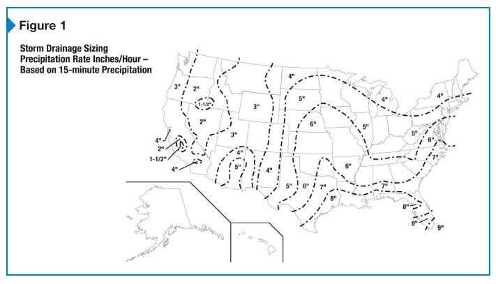
Each project location has its own historical rainfall data that include records of accumulation, intensity (i.e. duration and frequency), drop size, and terminal velocity. Rainfall intensity plays a significant role in determining the type, quantity, size, and placement of roof drains to be installed for optimal system design. (As every project is different, consultation with the roof drainage manufacturer is essential.)
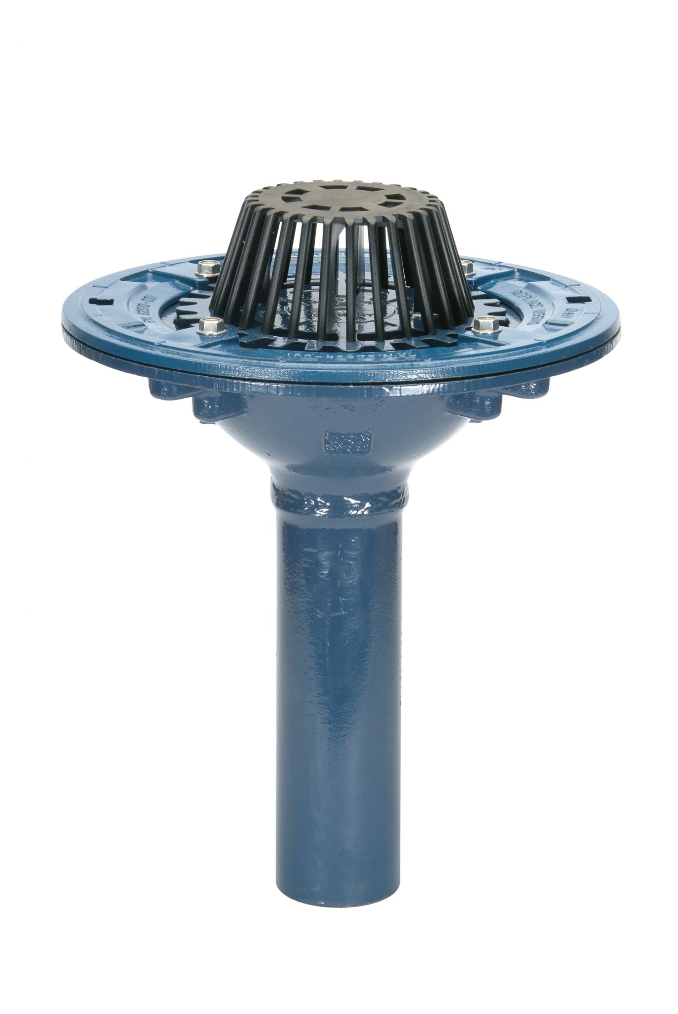
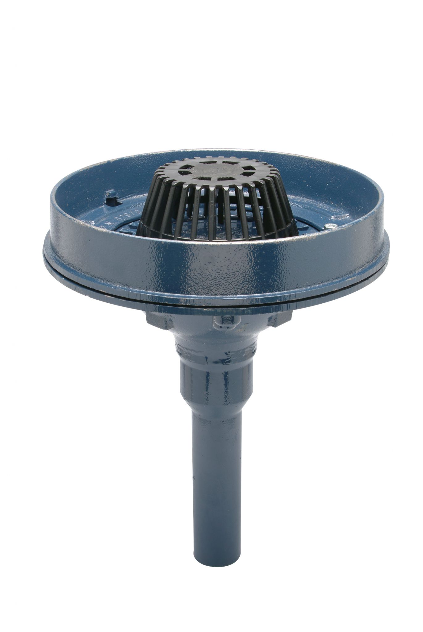
Figure 1 indicates the precipitation rates of numerous locations expressed in inches per hour and based on 15 minutes of precipitation (extrapolated from historical rainfall data collected over a period of 10 to 100 years). Reading this map, a design engineer would size a building drainage system in the Carolinas to handle a 178-mm (7-in.) hourly rainfall. Roof drain systems for most of New York State and Michigan would be sized to accommodate 102-mm (4-in.) hourly rainfall.
Traditional roof drains
Traditional roof drainage systems rely on gravity and water’s ability to spread out and flow to the lowest point. As the water accumulates, the depth increases and becomes the driving force causing it to flow through gutters to the roof outlets. Each outlet has its own down-pipe directing water underground. Unfortunately, as water enters the down-pipe, air is also drawn in, reducing the drainage system’s efficiency.
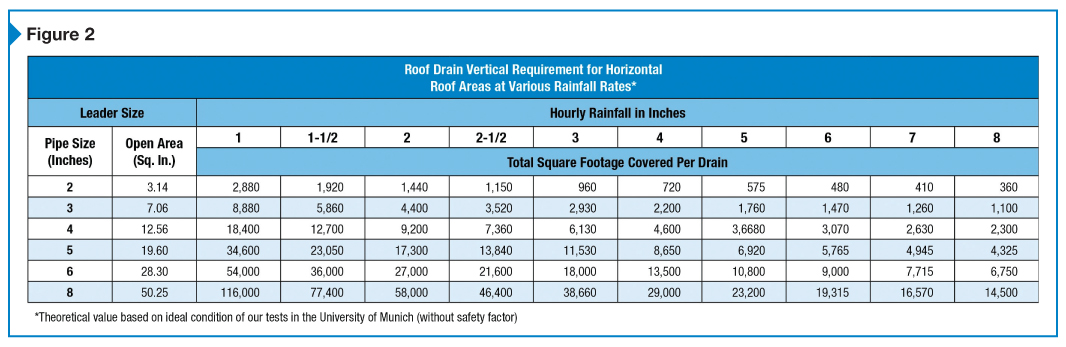
Figure 2 is a table to help size gravity roof drains by following these steps:
- Calculate total roof area.
- Determine and select the size of leader (i.e. roof drain, down-pipe, conductor, or downspout) to be used.
- Use precipitation map to find rainfall rate for building’s location.
- Cross-reference leader size with hourly rainfall in chart to obtain roof area that can be handled by each leader. For example, using a 102-mm (4-in.) leader for a location with a 102-mm hourly rainfall, each drain can handle 427 m2 (4600 sf) of roof area.
- Divide total roof area by area found in Step 4 to obtain the number of drains required. For example, 13,936 m2 (150,000 sf) divided by 427 m2 equals 32.6—this means 33 drains, equally spaced and symmetrically located.
Other non-siphonic roof drain systems
Regions affected by tropical storms or other severe weather phenomena make it necessary to transport large amounts of runoff water as fast and efficiently as possible. Designed for volume efficiency, high-capacity roof drains are more than 30 percent larger than standard ones. Careful consideration must be given to roof drain location and outlet pipe diameter.
Controlled flow roof drains are ideal for dead-level or sloped roofs, and for areas with restricted stormwater drainage capacity. With these drains, excess water accumulates on the roof under controlled conditions. The water is drained off at a metered rate after a storm abates. The key is to use a large roof area to temporarily store the maximum amount of water.
A controlled flow roof drain system requires fewer drains, smaller diameter piping, smaller sewer sizes, and lower installation costs. Another benefit is these systems reduce the probability of storm damage by lightening the load on combination sewers and reducing the probability of flooded sewers and backflow into basements and other low areas. The stored water on the roof also can act to temporarily improve the heat loss characteristics of the roof. To ensure success, designers and specifiers for controlled flow roof drainage design must carefully consider drain location, roof deflection, scupper sizes, overflow drains, and roof loading.
Siphonic roof drainage
Developed to operate with 100 percent full flow for increased discharge, smaller pipe diameters, and no drainage slope, siphonic roof drainage’s first commercial installation was at a Swiss turbine factory in 1972.
The theory behind siphonic roof drainage systems traces back to one of the fundamental equations of fluid mechanics—Bernoulli’s Energy Equation, named for the 18th-century Swiss mathematician and physicist Daniel Bernoulli. The energy balance equation holds when a fluid, at rest or in motion, possesses three fundamental forms of energy—static pressure, kinetic, and potential—the sum of their states is conserved and remains constant, even though the system energy states may be transferred from one to another.
The equation assumes the fluid is incompressible, that no work is done or performed on the system, and the system is adiabatic (i.e. no heat is gained or lost). It is used to determine change in flow between any two points in a drainage system. Numerous modifications of the equation have been made for specific applications. Siphonic theory itself has also undergone revisions to take into account losses due to friction in a length of pipe.
In their current design, siphonic roof drains look similar to conventional gravity roof drains; they share features such as a drain body, dome strainer, and membrane clamping device. The component unique to siphonic systems is the highly engineered air baffle.
The air baffle is secured into the sump of a standard drain, preventing vortex flow. In other words, it prevents the Coriolos Effect, which typically forces water to rotate around the drain and draw air down the center and into the pipe. By prohibiting air from entering the tailpipe and horizontal collecting piping, a negative head pressure is created in the collector pipe and the water is siphoned off the roof. The atmospheric pressure above the drain becomes the system’s driving force.
Location of the baffle in the drain sump is critical to the drainage system design. Locating the baffle lower in the drain body minimizes the amount of water on the roof that is required to make the drain go siphonic.
Once the rainwater is drawn through the drain and into the tailpiece, it then travels to the horizontal piping, located just below the roof. In this section of the system, the water continues to depressurize, and piping size increases to prevent cavitation or the pipe walls from imploding under the negative pressure. When the rainwater reaches the vertical stack, it stays at full bore flow but continues to pressurize as it moves downward to the zero point (i.e. siphonic break). The pipe turns down into a vertical downspout and transfers to conventional gravity drainage when below grade by expanding the pipe diameter.
The driving hydraulic head of the system is the entire height from the top of the roof to the discharge point, as opposed to a conventional system where only the roof water acts as a head pressure. Due to this, the siphonic system allows for higher flow capacities and velocities than a conventional system with the same sized piping. The higher velocities also mean a siphonic system can be considered ‘self-cleaning,’ eliminating the need for cleanouts in the piping.
Ideal applications
Siphonic roof drains provide full-bore flow when used in conjunction with a fully engineered/designed piping system. The full-bore action is achieved through natural hydraulic action. The system is designed to use the full volume of the piping—the water goes siphonic when the pipes are completely full.
Siphonic systems require fewer downpipes and smaller pipe sizes and need less space. This means greater design flexibility, reduced installation times, less material resources, and cost savings. They can be used on all buildings regardless of size, height, or exposure to rainfall. However, they are most efficient on low-rise buildings with large footprints, along with shopping malls and factories.
This is because in a siphonic system, the water moves through the horizontal piping at negative pressure, but increases in pressure as it drops vertically through the leader until the point it reaches zero pressure and transitions to gravity flow by increasing the pipe size. Since this transition typically happens after dropping only a few floors, most of the drop will be oversized gravity piping on a high-rise building—this excludes the traditional benefit of reduced pipe size for the entire building height. Further, the larger the footprint of the building, the more negative pressure can build up in the piping, which allows it to drop down the side of the building further before transitioning. Most high rises have smaller footprints and small roof areas—this does not allow a lot of negative pressure to build in the horizontal piping.
Specifying siphonic roof drainage
In the United States, the standard siphonic drain is 380 mm (15 in.) in diameter. Outlet sizes include 50-, 76-, and 102-mm (2-, 3-, and 4-in.) no-hub mechanical joint connections. Drains and clamp collars can be made from iron or stainless steel, while domes are made from polypropylene, aluminum, bronze, or iron. Specifiers should consider using stainless steel vandal-proof hardware to help reduce corrosion in the assembly.
A siphonic system is available with many of the basic, conventional roof drain options. Mounting devices such as deckplates are recommended to help speed installation. A drain riser and adjustable extensions assist in leveling the roof drain during construction. For gravel rooftop applications, a gravel guard can help ensure proper drainage. If desired, an overflow drain can be used with standard siphonic systems to connect to a separate drain line, discharging to an outside location instead of a sewer.
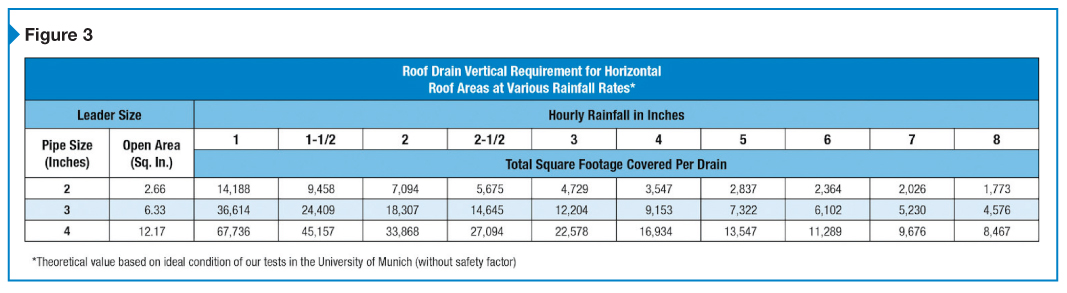
Determining the number of siphonic roof drains needed is similar to the same process for conventional roof drains (Figure 3). First, one decides what outlet size is needed (left column) and what rainfall rate is necessary (rows across). Then, one finds the number in the box where the column and row values meet. The number is the square footage each siphonic drain can cover under those conditions.
When comparing the siphonic to the conventional roof drain sizing chart, it becomes apparent the siphonic pipe size will be roughly half of a conventional drain covering the same area. (The chart should be used for a preliminary estimate, and should not take the place of consulting a manufacturer’s engineering or technical staff for complete piping layout.)
Another important step is to check the local plumbing code to see whether a rainfall rate is dictated and if siphonic drainage systems are addressed. In many cases, plans will need to be submitted as an engineered system or variance. A licensed professional engineer must verify the system will work as designed.
Siphonic design guidelines
Siphonic design software is now used to design and calculate if minor changes during installation fall within the design’s acceptable range of pressures and velocities in the piping. The aforementioned ASPE/ANSI 45-2013 should be reviewed to determine how installation differs from a conventional drain system. One main difference is the use of eccentric reducers whenever there is a change in pipe diameter. These help maintain a flat surface along the top of the pipe, eliminating any air pockets.
No more than 4645 m2 (50,000 sf) of roof area should be tied into one common collector pipe (otherwise, the system can be very hard to balance due to the large distance between drains and large pipes used). Further, roof areas made from different types of roof materials should not be tied into a common collector pipe. These roof materials have different coefficients of discharge, and would not be able to draw a siphon at the same time if tied into the same pipe. (Different fittings can also have dissimilar coefficient of friction ratings—software should be used to select the most appropriate type of transition.) Roof areas with extreme variation in slope, or roof areas at different roof levels, must also drain into separate collector pipes.
One must avoid not only multiple vertical drops in a single piping system, but also piping below an obstruction. Both these issues would delay the system from priming, slowing it from going siphonic.
Every roof trough must have at least one siphonic drain present in that area. When initially designing a system, drains tied to a common collector pipe should be spaced no more than 20 m (65 ft) apart, and stacks should be located no more than 20 times the building height away from the furthest drain. However, these dimensions are only guidelines—they can be increased if the system can be properly balanced. Pipe lengths longer than 20 m should be divided into smaller sections to accurately determine where the pipe diameter can increase from one size to the next.
At least 1 m (3 ft) must be maintained between the surface of the drain and the center of the horizontal collector pipe. Tailpieces attached to the bottom of the drain must be at least 0.5 m (21 in.) long before tying into the horizontal pipe.
For siphonic systems, each individual and total system rating must fall between negative 10.13 kPa (1.47 psi) and positive 10.13 kPa. It is important for overall imbalance of the system be as close to zero as possible. Cast iron or polyvinyl chloride (PVC) piping can withstand a minimum pressure of negative 90 kPa (13 psi). If pressure is too low, pipe diameter must be increased to relieve pressure.
The flow rate of the ‘zero pipe’—the first section of pipe after the siphon has been broken and the transition to gravity drainage has been made—must be less than 2.5 m (8 1/4 ft) per second to prevent damage to the storm sewer. In many cases, flow rate is reduced to around 1 m (3 ft) per second to align with traditional pipe sizes based on the roof area and the rainfall rate. (This flow rate is the minimum for ensuring the system remains self-cleaning.)
Conclusion
This system of roof drainage is beginning to gain traction in the United States. Statistics are difficult to come by, but the wide acceptance of siphonic roof drainage in Europe and other parts of the globe provide reassurance and a backdrop of success. The key for any project, including those involving siphonic roof drainage, is to ensure one deals with reliable manufacturers with track records for delivering engineered solutions. Since every project is different, consultants must be willing and able to give the time and expertise required.
William Verdecchia is the director of product management and engineering for Zurn Specification Drainage. He has more than 25 years of experience in the construction industry; with five years as a construction professional and 20 years leading innovation, product commercialization, and sales/marketing activities for Zurn Industries. In his current role, Verdecchia oversees product lifecycle management activities and application support for plumbing products. He has been awarded numerous plumbing industry patents and is an active board member for the Plumbing and Drainage Institute, Penn State Behrend’s Plastic Engineering Program, and Gannon University’s Mechanical Engineering Program. He can be reached at william.verdecchia@zurn.com.


Just read your article in Construction Specifier.
I am looking into installing siphonic drains on the industrial buildings we design. The buildings can be anywhere in the world so rainfall will vary considerably. These are pre-engineered metal buildings with a standing seam metal roof sloped at 4% to 5%. Buildings are typically ~13,000 m2. Half the roof drains to one side, half to the other side into gutters. Until now, always used 6” downspouts spaced per local rainfall records.
Can you comment on a couple items?
• What effect is there if I spec too high rainfall amount? Does that affect performance of the siphon? If so, is there a way to mitigate that, inlets at different elevations?
• These siphonic drains will be installed in gutter. Does that present any special design/installation problems other than drain must fit inside the gutter?
BTW, I’ve done some reading on siphonic drains and you are the first I’ve noticed to mention eccentric fitting when changing pipe diameter. I am sure you are correct it is good practice.
Best regards,
Harry