

by Ulf Wolf
Between January of 2005 and June of 2007, the Oak Ridge National Laboratory (ORNL) undertook an extensive EIFS Industry Members Association (EIMA)-sponsored trial comparing the moisture and temperature management properties of several exterior insulation and finishing system configurations with those of other claddings in a hot and humid climate. Now, a new third phase of the study is demonstrating the assembly’s potential for other climate zones.
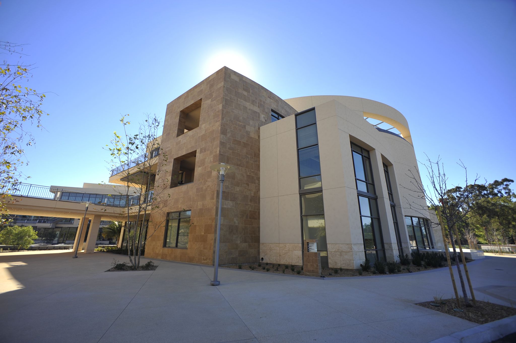
As part of Phase I of the initial study, researchers designed and built a test facility in Hollywood, South Carolina near Charleston—a location typical of a mixed, coastal, Zone 3 climate, as prescribed in the 2006 International Energy Conservation Code (IECC). The flexible design allowed researchers to change the wall panels with ease and to control conditions inside the building by creating two zones within the building interior.
Interior temperature and relative humidity (RH) conditions were selected based on the proposed American Society of Heating, Refrigerating, and Air-conditioning Engineers (ASHRAE) SPC 160P, Criteria for Moisture Control Design Analysis in Buildings. Building orientation and placement of the wall panels were determined based on a comprehensive study of historical weather patterns, including prevailing wind and precipitation direction.
The data were collected in two phases. In Phase I, 15 exterior cladding configurations—not only EIFS, but also stucco, brick, and cementitious paneling—were integrated into one side of the building (southeastern exposure), with the goal of having all the claddings exposed to similar weather conditions for a full weather year (15 months from January 2005 through May 2006).
In Phase II, simulated building envelope defects were introduced into some of the wall panels, which included newly constructed wall panels as well as some of the 20-month-aged wall panels from Phase I. (To simulate leaks, these defects allowed a certain amount of water to penetrate the outer envelope.) The goal was to assess the performance of cladding assemblies to water penetration, as well as the impact on the performance of wall assemblies from wall orientation on moisture infiltration, the type of water-resistive barriers (WRBs) used (e.g. sheet membranes versus liquid-applied), and different exterior cladding systems (e.g. EIFS and brick). In Phase II, wall panels were placed on both the building’s southeast and northwest sides, with data collected from May 2006 to June 2007.
 Zone 3 conclusions
The findings of these trials, as published at the time, showed EIFS was capable of controlling temperature and moisture within the wall system; it also showed these assemblies outperformed other exterior claddings during the monitored year. Phase II further established that an EIFS system, with drainage consisting of a liquid-applied water-resistive barrier coating and 100 mm (4 in.) of expanded polystyrene (EPS) insulation board, performed the best of all tested systems.
In other words, given the specific parameters of this study, the EIFS wall configurations performed better than stucco (both three- and one-coat) and brick. The EIFS wall systems with drainage maintained a consistent, acceptable level of moisture (average monthly RH below 80 percent, as defined by ASHRAE SPC 160P) within the cladding, despite varying outdoor conditions when appropriate interior vapor retarders were used. Brick and stucco tended to accumulate slightly more moisture during both Phase I and Phase II of the project and retained moisture longer than EIFS.
The trial also found EIFS with a liquid-applied, water-resistive barrier coating readily dispersed moisture introduced by the building envelope flaws installed for Phase II, unlike other claddings that retained more water. Both Phase I and II trials also confirmed vertical ribbons of adhesive provide an effective means of drainage within an EIFS-clad wall assembly.
 The research showed EIFS has the ability to maintain the acceptable balance of moisture and temperature control indicative of a well-designed, properly operating, energy-efficient building without moisture problems. To quote the ORNL report summary:
EIFS-clad wall assemblies with drainage outperform other typical exterior claddings during most of the year. The results also showed that EIFS is an excellent exterior cladding choice for achieving key building performance goals in a hot and humid climate, specifically a mixed, coastal, Zone 3 climate.
These trials, however, did not necessarily answer the questions or concerns any designer, contractor, or insurer operating outside mixed, coastal, Zone 3 might have about EIFS. In other words, how does it perform in Zones 1 to 2 and 4 to 8? This is where Phase III of the ORNL trials enters the picture.
ORNL trials’ Phase III
Having compiled the full data set from Phases I and II for the mixed, coastal climate, the task remained to extrapolate these findings across all U.S. climatic regions. One way to achieve this would have been to select sites in the various climate zones and constructed additional test facilities there for live data-collection. This, however, would have been neither practical nor cost-efficient. Rather, the task fell to ORNL (more specifically, program manager Andre Desjarlais) to create a reliable, computer-simulated trial for the remaining climate zones. Desjarlais’ reports, and a recent interview with this author, has provided the overview and summary of this third phase of the EIMA-sponsored EIFS trials in this article.
Running a computer simulation of this kind requires two virtual constructs validated as behaving and performing like real-world ones. First, there are the virtual panels, which are the computerized equivalent of the real-life, constructed panels used in the Phase I and II trials. Then, there are also the virtual climate zones—the computerized equivalent of the real-life humidity levels and weather patterns of actual climate zones.
The simulation consisted of creating four virtual panels (each fully corresponding to its live counterpart), which were then placed in each of the eight different virtual climate zones. They were then virtually exposed over three simulated ‘years’ to the humidity fluctuations and weather conditions of each respective zone. At the same time, the same hygrothermal measurements of these panels, as had been monitored during the live trials, were taken:
- temperature;
- relative humidity (RH);
- heat flux; and
- moisture content.
By the end of these simulated trials, ORNL had collected performance data equivalent to four different panels in eight different locations over three years.
 The software tool
Virtual panels and climate require validated software tools to construct them. The tool used for this third phase of the trials was WUFI, which stands for Wärme und Feuchte Instationär (i.e. heat and moisture fluctuations)—a true and tested software tool long used to calculate the coupled heat and moisture transfer in building components.
This PC program allows realistic calculation of the transient coupled one-dimensional heat and moisture transport in multi-layer building components exposed to natural weather. WUFI is based on the latest findings regarding vapor diffusion and liquid transport in building materials and has been validated by detailed comparison with measurements obtained in the laboratory and on outdoor testing fields. The underlying model has been validated for more than 20 years.
WUFI, like the live study, takes into account not only thermal properties of a building component and their impact on heating losses, but also its hygric (moisture) performance since thermal and hygric behavior of a building component are closely interrelated—increased moisture content leads to heat loss, while thermal situation in turn affects moisture transport. Therefore, both have to be tracked in their mutual interdependence for an accurate result. WUFI accomplishes this.
 Virtual panels and locations
Following the guidelines summarized in ASHRAE 160-2009, Criteria for Moisture-control Design Analysis in Buildings, each simulation was undertaken for a three-year period using the design ‘cold’ year. Four wall systems were selected for study, comprising the following components:
- EIFS Panel 2 (P2): 40-mm (1 1/2-in.) flat insulation, notched trowel attachment, drainage airspace created by vertical ribbons, liquid-applied weather barrier, plywood exterior sheathing, 50 x 100-mm (2 x 4-in.) framing 400-mm (16 in.) on center (oc), with unfaced R-11 fiberglass batts and no vapor retarder, a 13-mm (1/2-in.) gypsum board, and a 10-perm paint layer;
- EIFS Panel 5 (P5): 100-mm (4-in.) flat insulation, notched trowel attachment, drainage airspace created by vertical ribbons, liquid-applied weather barrier, plywood exterior sheathing, 50 x 100-mm (2 x 4-in.) framing 400-mm (16 in.) oc, with no cavity insulation and no vapor retarder, a 13-mm (1/2-in.) gypsum board, and a 10-perm paint layer.
- EIFS Panel 11 (P11): 40-mm (1 1/2-in.) flat insulation, notched trowel attachment, drainage airspace created by vertical ribbons, a liquid-applied weather barrier, ASTM C1177 exterior gypsum board,1 18-gauge 50 x 100-mm (2 x 4-in.) steel framing 400-mm (16-in.) oc, with unfaced R-11 fiberglass batts and no vapor retarder, a 13-mm (1/2-in.) gypsum board, and a 10-perm paint layer; and
- brick Panel 14 (P14): brick façade, 25-mm (1-in.) airspace, one layer of Grade D 60-minute building paper, oriented strandboard (OSB) exterior sheathing, 50 x 100-mm (2 x 4-in.) framing 400-mm (16 in.) oc, with unfaced R-11 fiberglass batts and no vapor retarder, a 13-mm (1/2-in.) gypsum board, and a 10-perm paint layer. Airspace was considered ventilated (open top and bottom).
 The eight IECC climate zones modeled in this simulation (representing cities for Climate Zones 1 through 8, respectively) were:
- Miami, Florida;
- Austin, Texas;
- Atlanta, Georgia;
- Baltimore, Maryland;
- Chicago, Illinois;
- Minneapolis, Minnesota;
- Fargo, North Dakota; and
- Fairbanks, Alaska.
Model validation
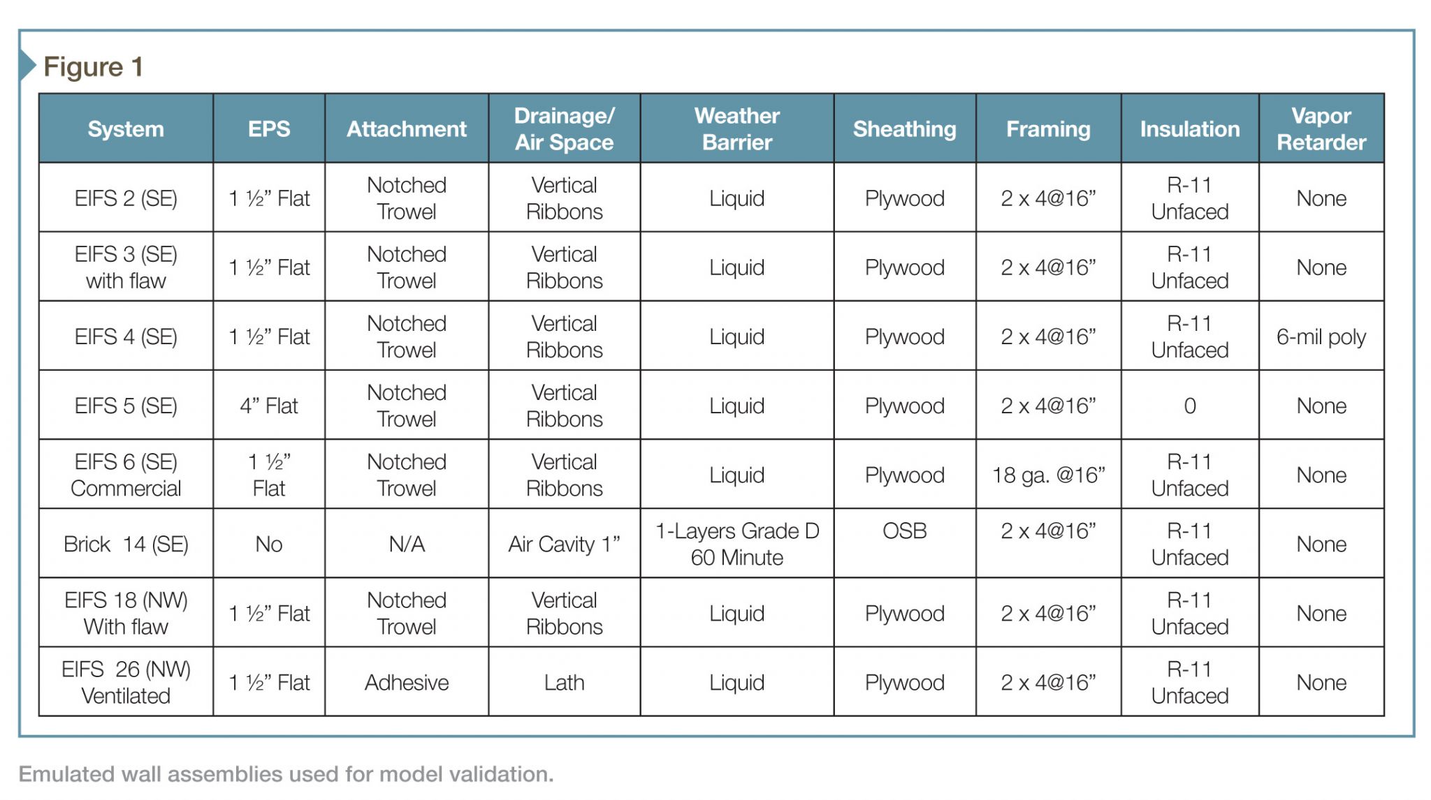
The first step of this simulation was to validate the model itself—that is, to ensure the virtual panels behave precisely like their real counterparts, given the same hygrothermal loads. For purposes of validation, the researchers selected eight different panels from Phases I and II to emulate with computer configurations. The panels chosen for this, and their makeup, are shown in Figure 1, which is taken from the ORNL report, “Energy and Moisture Impact on EIFS Walls in the USA.” (Note: The typical interior finish for all emulated systems was 13-mm [(½-in.)] drywall, primed and painted [one coat of acrylic paint]).
 The validation of these eight selected wall systems ran for the combined length of Phases I and II and was performed using the measured Natural Exposure Test facility (NET) weather station data for Charleston, South Carolina, along with the measured indoor data, and all hygrothermal material properties measured during Phases I and II of this trial.
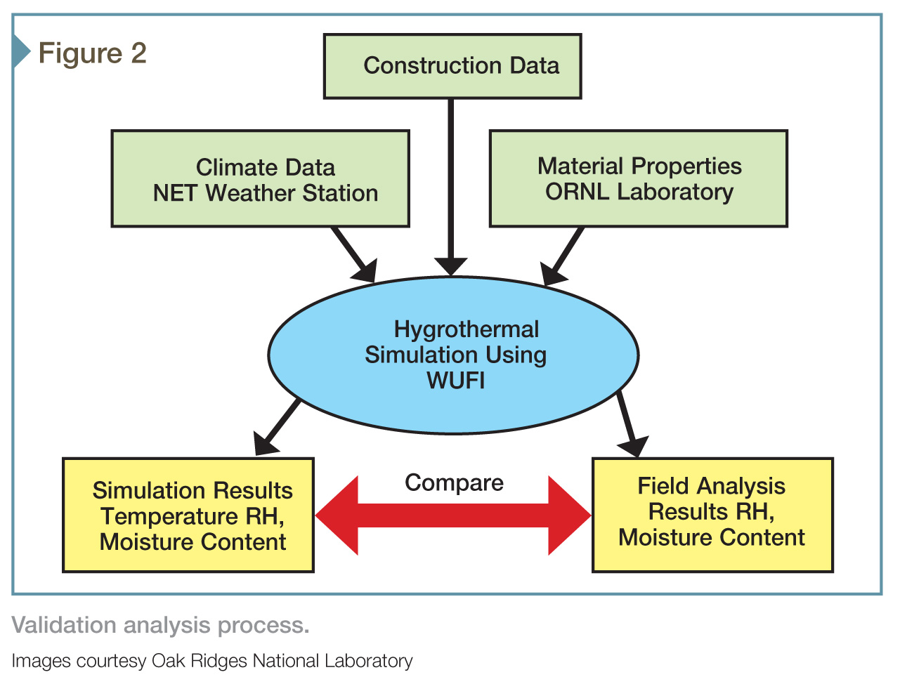
Figure 2 illustrates the validation process. Completed, this analysis demonstrated good agreement between the WUFI hygrothermal model and the Charleston South Carolina field data, the model trends at all times following those of the Phases I and II experimental data. Consequently, the researchers could now confidently predict the heat and moisture performance of the four walls systems selected for the final simulation.
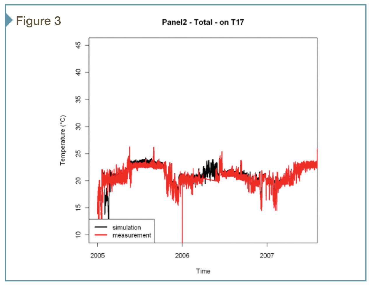
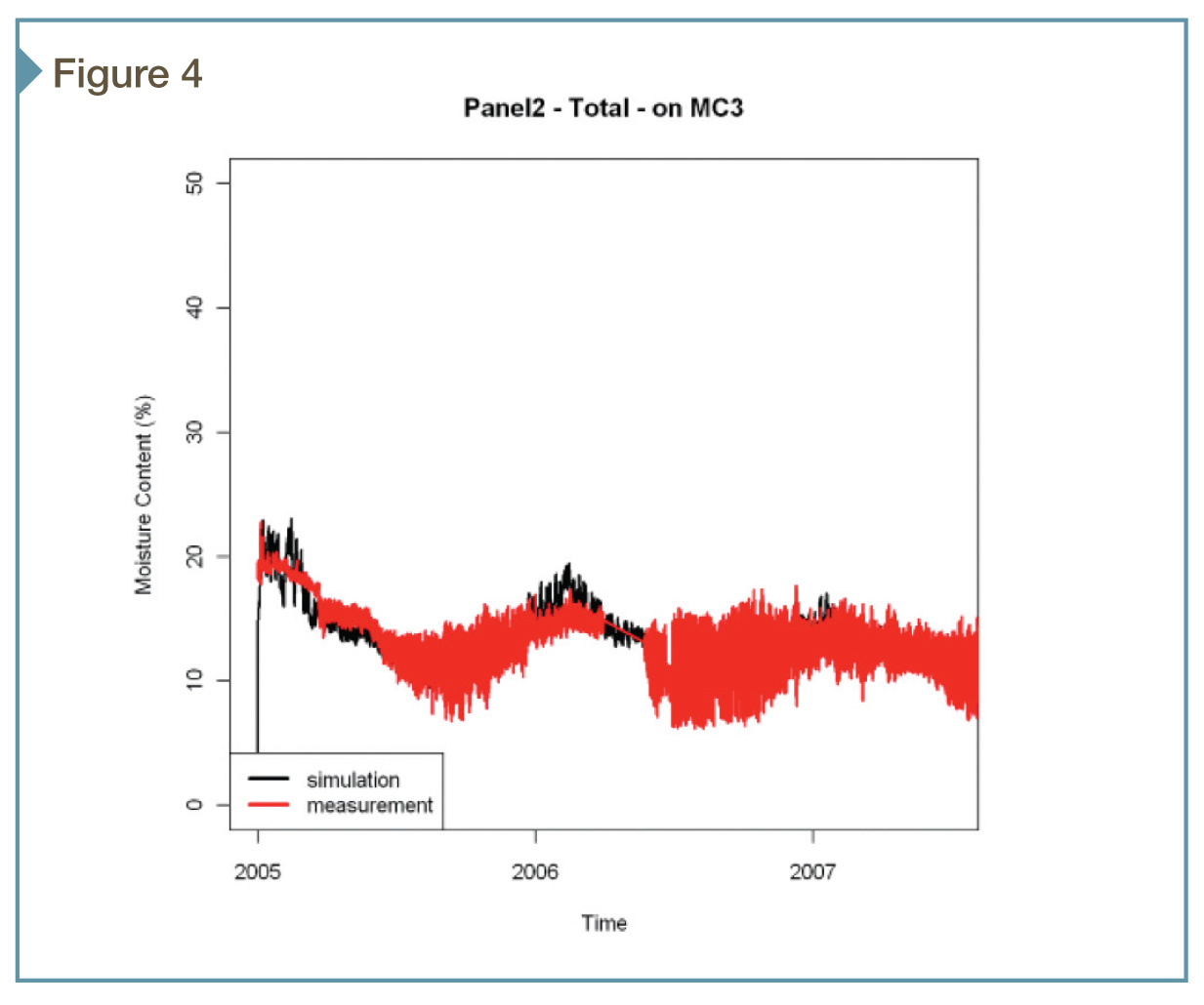
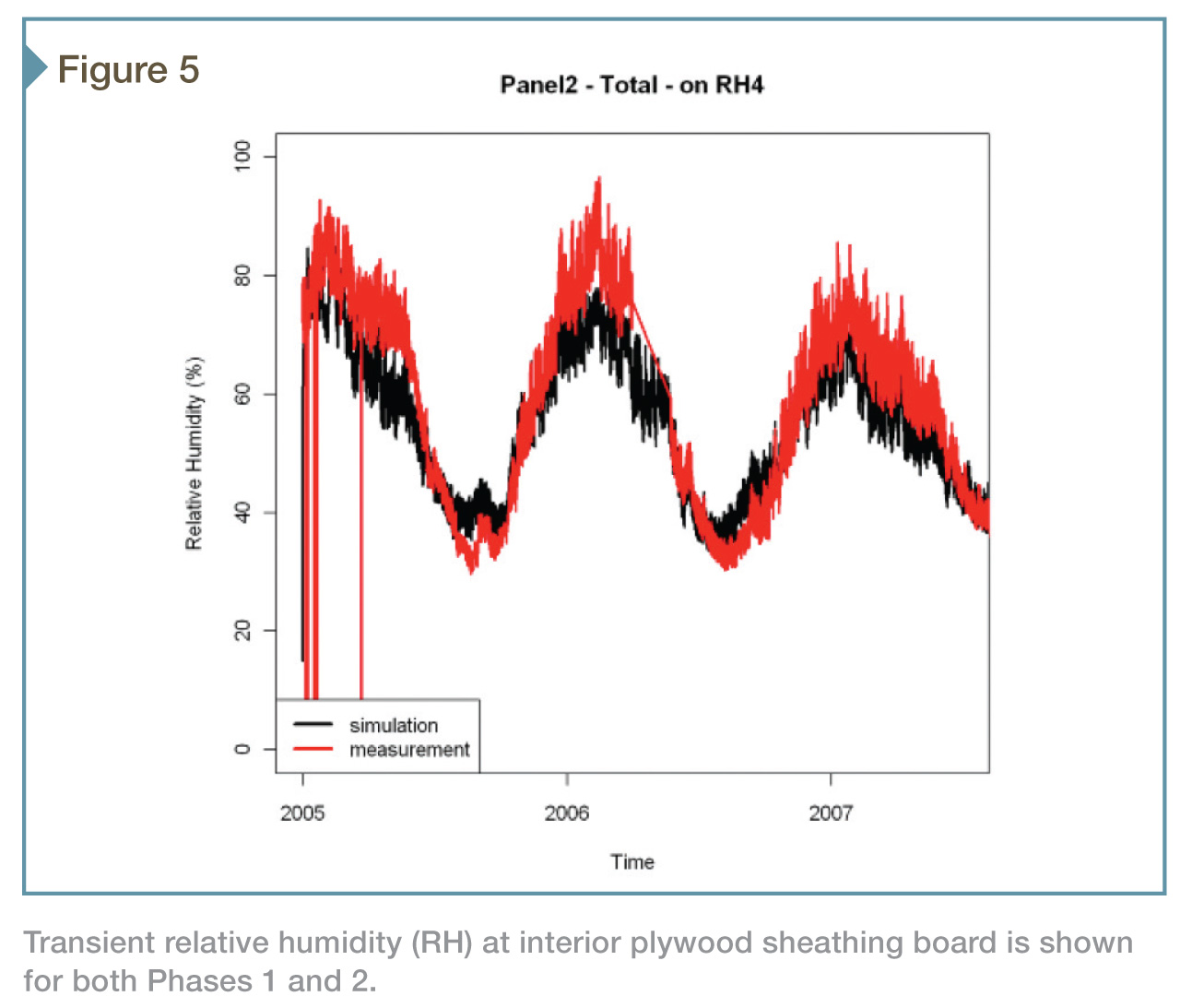
Figures 3 through 5 illustrate the type of data collected during the validation phase. EIFS Panel 2 is used as an example in this case. These figures depict both the measured and predicted (simulated) factors as follows:
- Figure 3—interior surface temperature as measured by Thermistor 17 (T17);
- Figure 4—moisture content of the plywood sheathing as measured by Moisture Content Sensor 3 (MC3); and
- Figure 5— relative humidity of the interior surface of the plywood as measured by Relative Humidity Sensor 4 (RH4).
In all instances, the predicted parameters satisfactorily agreed with the measured results.
 The simulation
Using the validated model, the researchers now performed a hygrothermal WUFI analysis following the guidelines summarized in ASHRAE 160-2009. Each simulation was undertaken for a three-year period using the design ‘cold’ year. As mentioned, the four wall systems studied were identified as P2, P5, P11, and P14.
Each wall system was evaluated with and without a vapor retarder, and with and without water penetration as specified in ASHRAE 160-2009. Traditional practice does not typically require a vapor retarder in the southern climates, but these wall systems were modeled as well for completeness.
The wall orientation provided the maximum amount of rain to emulate water penetration. Therefore, whenever rainfall was detected, one percent of the rain incident on the exterior surface of the wall system was deposited into the wall’s exterior sheathing.
The interior boundary conditions were developed as per ASHRAE 160-2009 and the initial moisture contents of all wall components were set at their equilibrium moisture content at 80 percent RH. Solar radiation and cooling due to night sky radiation were included in the analyses.
Resulting data
The volume of data generated by these simulations cannot adequately be summarized in a short article. To trim the data down into a digestible portion, the results of Climate Zone 6 (Minneapolis) will be the focus—however, it is representative of the data generated by remaining seven Climate Zones.
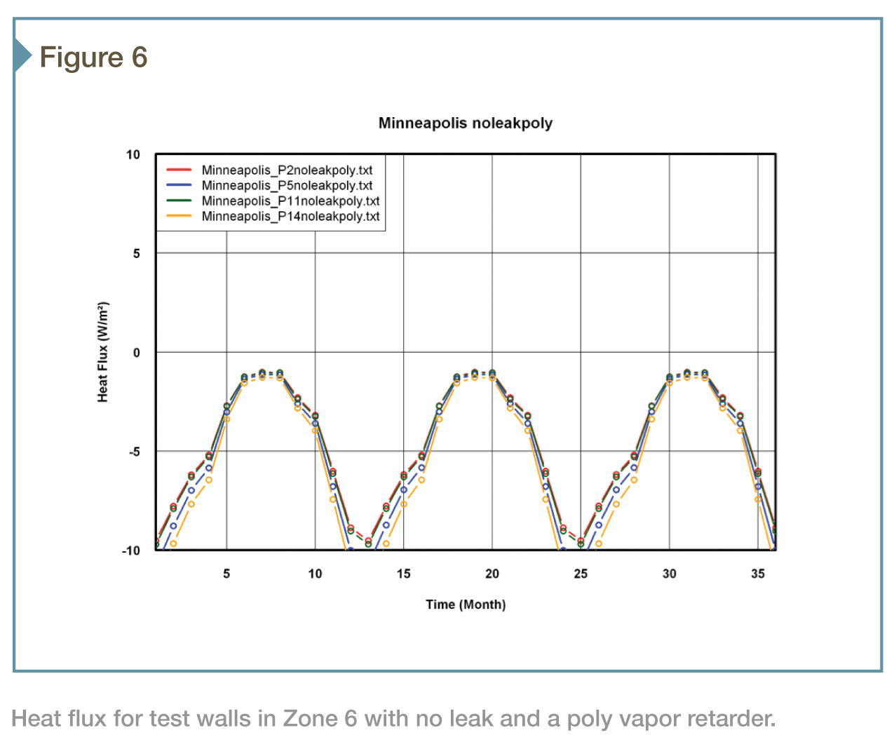
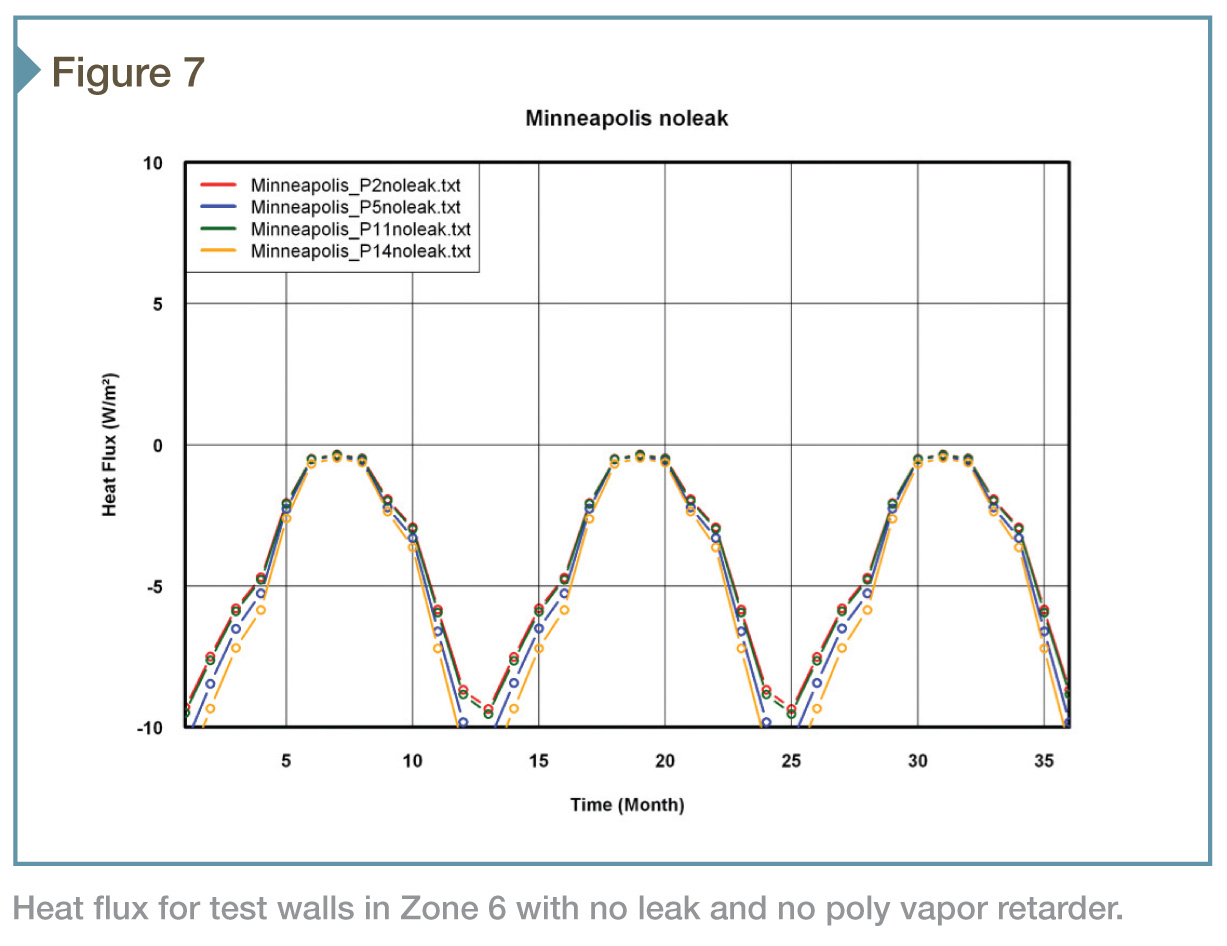
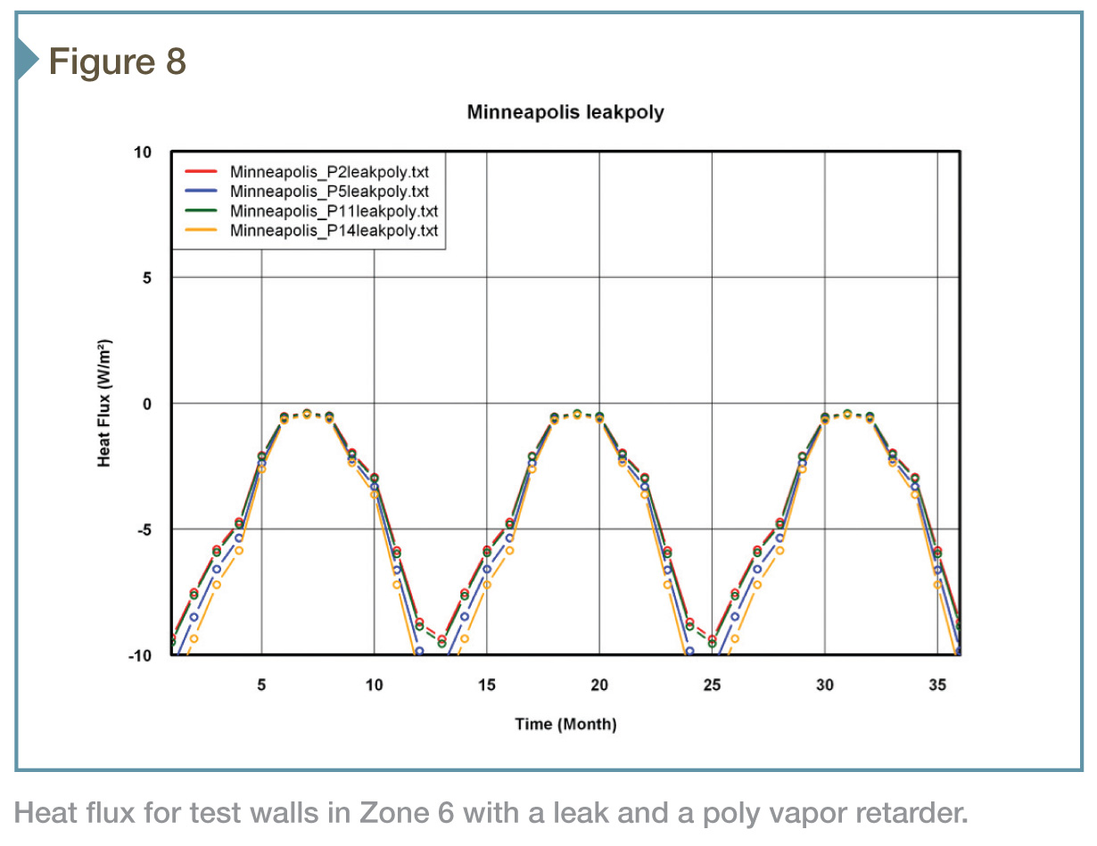
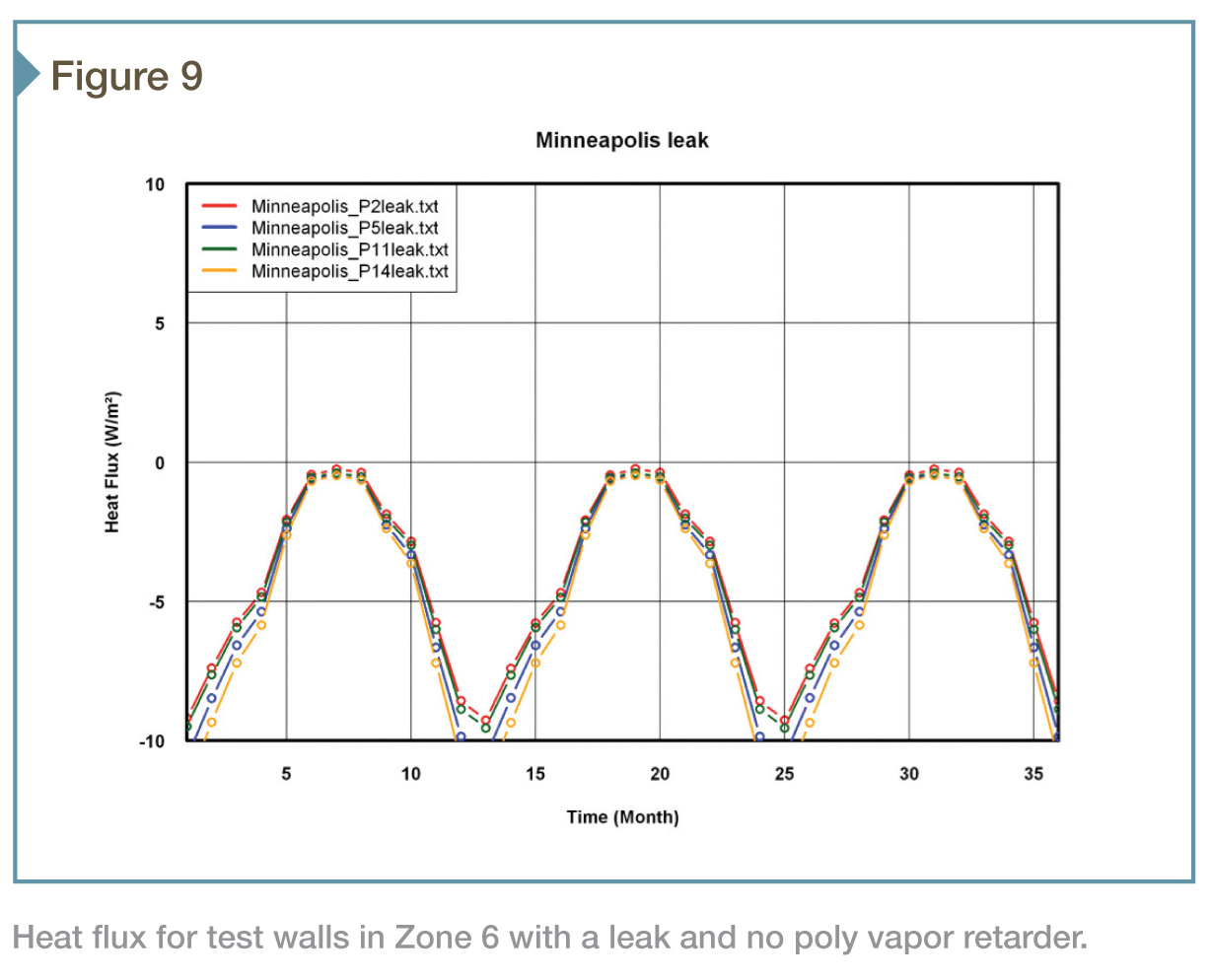 Figures 6 through 12 summarize the monthly average heat flux through the four wall systems, and the moisture content of their exterior sheathings in Climate Zone 6 weather conditions over a three-year period. The four pairs of graphs compare the effects of leakage (none vs. ASHRAE 160) and the inclusion of a vapor retarder (none vs. 6-mil poly).
It is important to note EIFS configurations P2 and P11 yield the same energy efficiency, followed by EIFS P5 and Brick P14. The addition of leaks and vapor retarders does little to modify the energy performance of these walls in this climate; the walls are hygrothermally efficient enough to prevent sufficient moisture accumulation to impact their energy efficiency.
With no leakage and no poly, all wall systems maintain exterior sheathing moisture contents well below 80 percent RH. The addition of poly has little impact on the moisture contents. Wall EIFS P5 outperforms the other wall assemblies; the low interior RH maintains the exterior sheathing to a very low level of relative humidity.
When leakage is added to the wall assemblies in this climate, their hygrothermal performance changes minimally. Both configurations do add to the moisture contents of the walls’ exterior sheathings, but they are maintained at moisture content levels at or below the 80 percent RH level.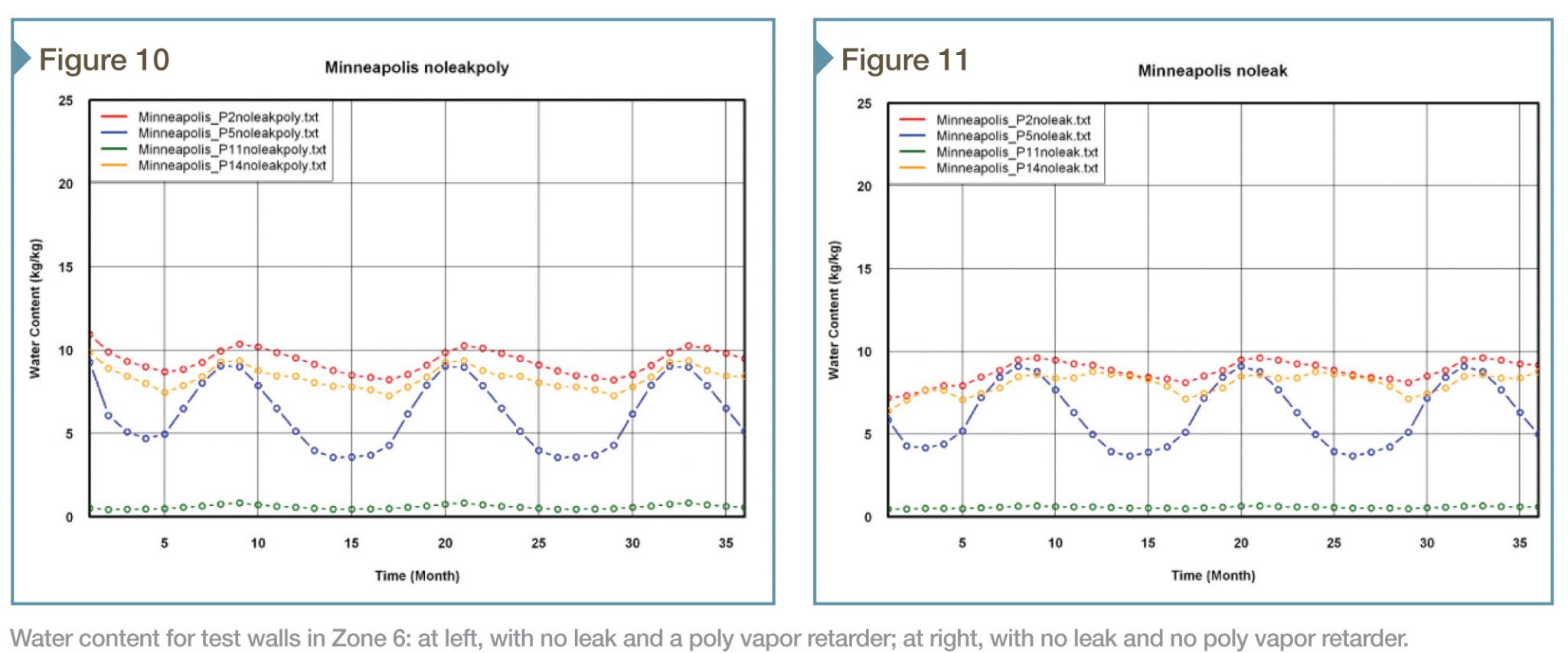
Energy efficiency
For all climate zones, the addition of the leak did not appreciably increase the heat flux. Adding a vapor retarder on the inside of the test walls, which would retard the internal drying potential or decrease the moisture flow from the building interior, did not change the moisture contents of the walls enough to affect their energy efficiency.
The researchers found little difference in the heat flux through the four test walls in Zone 1. Moving the wall systems to colder climates, EIFS Panels 2 and 11 exhibited the best energy performance, followed by EIFS Panel 5 and Brick Panel 14. The facts the simulations are one-dimensional—and the calculations are performed in the center of the cavity—explain why one sees no effect of the metal studs in EIFS Panel 11. The differences between EIFS Panels 2 and 11 and the other two test panels increase in colder climates.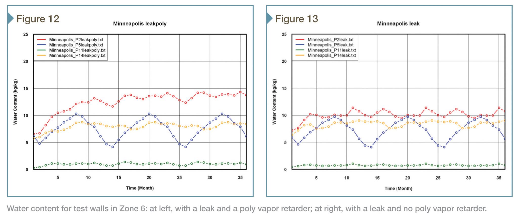
Moisture performance
For all climate zones, panels combining no leakage and no vapor retarder deliver acceptable performance. That is also true for all panels with no leakage and a poly vapor retarder. The addition of the vapor retarder increases the sheathing moisture contents for all walls in the warmer Climate Zones 1 through 4, but this addition is relatively small and on the order of two to three mass percent—in other words, not enough to compromise the durability of the wall systems. In the more northern zones, the addition of a vapor retarder is neutral; all panels behave similarly with or without the vapor retarder.
The addition of a leak substantially increases the moisture contents of all wall assemblies. In Climate Zones 1 through 4, the panels without a vapor retarder come close to the 80 percent RH threshold (levels above 80 percent for extended periods are detrimental).
When a vapor retarder is added, the moisture contents rise even further and are at levels above 80 percent RH for months each year and as systems will eventually fail. In colder Climate Zones 5 through 8, the increase in moisture content after adding a vapor retarder is less severe, and the time the sheathing is at moisture contents exceeding 80 percent RH is substantially shorter.
Conclusion
Throughout the simulation, the three exterior insulation and finishing system configurations outperformed the brick wall system for the specific measured criteria across all climate zones, with EIFS Panel 5 performing the best overall. Joseph Lstiburek, an ASHRAE fellow and a principal at Building Science Corporation, was one of the first forensic engineers to sound the alarm over moisture buildup problems within barrier EIFS in the late 1980s. At that point, he did not think highly of the assemblies. This, however, has changed over time, and today he confirms he believes EIFS to be “a phenomenal system. They addressed the fundamental flaws they had in the 1990s by adding moisture management. And now EIFS resembles the perfect wall.”2
When considering the research in this article, it is important to remember all ‘test walls’ were constructed new. A test like this will not highlight differences 20 years down the road. Further, a scientific tracking of various actual envelopes built in many climate zones as to moisture and thermal performance, as well as to insurance costs and claims, will paint a broader, fuller comparative picture amongst claddings. Finally, this study was intended to measure only the moisture and thermal performance of these wall assemblies—there are other criteria design/construction professionals and building owners will take into consideration when selecting materials for their projects.
With both the 2012 IECC and ASHRAE 90-1 now stipulating continuous insulation building envelope for new construction, the outcome of this third and final phase of the ORNL trials is very good news indeed for EIFS.
Notes
1 This is per ASTM C1177, Standard Specification for Glass Mat Gypsum Substrate for Use as Sheathing.
2 For more, see the August 2013 issue of Architect, which featured the article, “Water Under the Bridge,” by Elizabeth Evitts Dickinson. Visit www.architectmagazine.com/technology/water-under-the-bridge.aspx. (This author recently spoke with Lstiburek and confirmed his quotation still stands.)
Ulf Wolf is the senior writer at Words & Images (www.words-images.com). Since 2007, he has been a regular contributor of articles to the Association of the Wall and Ceiling Industry’s (AWCI’s) Construction Dimensions magazine. Previously, he contributed “Greener Than You Think: Exterior Organic Solvent-based coatings” to the February 2011 issue of The Construction Specifier. He can be reached via e-mail at ulfwolf@gmail.com.


Do you have a PRODUCT that will be the EXACT layers and steps for an EFIS exterior surface for a BUILDING ?
Need as SAFE as possible and NO OUTGASSING form boards and Base and Back Stop and Sand Pebble Finish that is truly
ORGANIC in nature or as CLOSE to that concept ?