Issues with waterproofing blind-side shotcrete foundation walls
by sadia_badhon | February 19, 2020 10:02 am
by Stacy Byrd, CDT, and Kevin P. Kling
 [1]
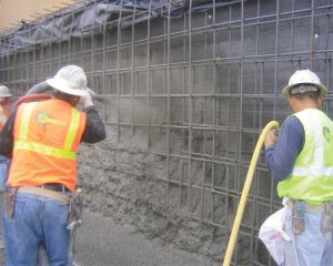
[1]Below-grade construction with shotcrete is gaining popularity across the country. The trend of using shotcrete instead of conventional cast-in-place (CIP) concrete can be attributed to the lower construction cost and time saved by not having to place and remove formwork. However, the use of shotcrete has resulted in a higher incidence of water ingress in below-grade foundations. This appears to be greatest on projects where conventional CIP concrete is value engineered out to shotcrete after the bids are awarded. One may argue this, in part, could be the result of not reviewing or updating the waterproofing system details—initially designed for CIP—for the application conditions associated with shotcrete.
Defining shotcrete
Shotcrete is concrete conveyed through a hose and pneumatically projected at a high velocity on a surface to achieve consolidation. According to the American Concrete Institute (ACI), structural shotcrete has a specified compressive strength of 28 MPa (4000 psi) or greater. It is further defined by the size of the aggregate used, with maximum aggregate grading typically being 13 mm (1/2 in.). Shotcrete can be applied by two processes: dry-mix and wet-mix. With dry-mix shotcrete, dry concrete materials are blended and dampened, placed into delivery equipment, and then conveyed through a hose with compressed air where water is added at the nozzle as the mix is applied. For wet-mix shotcrete, the concrete materials are mixed with water prior to the delivery equipment, and then conveyed through a hose by positive displacement to the nozzle where compressed air is introduced as the mix is applied.
An advantage with the wet-mix process is the ability to better control proportions of the cement, aggregate, and water to maintain mix consistency. Since shotcrete is placed with a high cement to water (c/w) ratio (low slump), it does not require conventional forming. Most structural shotcrete on commercial construction projects is installed using the wet-mix process.
 [2]
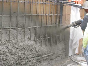
[2]Shotcrete is typically applied from the bottom up to compact and consolidate the working lift. The top of each lift is shaped at a typical one-to-one downward slope. The velocity of the wet-mix shotcrete on ejection from the nozzle is usually around 20 to 30 m/s (65 to 100 ft/s). Structural shotcrete is typically applied at a rate of 4 to 11 m3 (6 to 15 cy) per hour and 203 to 610 mm (8 to 24 in.) wall thickness.
Shotcrete lift height should be limited to approximately 1.2 m (4 ft) to prevent sloughing and sagging. Successive lifts are placed when the previous one has sufficiently set and developed strength to support the next one’s weight. This process then is repeated until the entire foundation wall is placed.
Curing methods of shotcrete vary from no curing to keeping the surface as moist as possible with water and curing blankets for at least seven days to minimize the shrinkage cracking that can form due to the high c/w ratio.
Shotcrete versus CIP
Although the structural properties of shotcrete can be designed to be equivalent to conventional CIP formed concrete, there are potential challenges with the former, especially waterproofing performance. These water ingress challenges can occur with either positive-side membrane systems or with admixtures added to the shotcrete.
A big advantage with conventional CIP formed concrete is that when placed, the fluid material develops sufficient lateral confining pressure to position the waterproofing membrane against the property-line shoring wall. Additionally, the plastic concrete is vibrated to solidify, thus removing poorly consolidated pockets and assisting the material to flow around and encapsulate reinforcing steel and other structural and mechanical elements. Another advantage is conventional formed concreting does not require the same level of reinforcement stabilization as with shotcrete, so there is no need to pierce the waterproofing membrane with fasteners, thereby eliminating hundreds, if not thousands, of punctures.
With shotcrete, there is less lateral confining pressure on the waterproofing membrane than CIP concrete due to the low slump in which it is applied. Further, without vibrating the shotcrete, voids behind the reinforcement steel and rebound pockets remain unconsolidated. These issues are exacerbated with congested reinforcement steel.
Proper consolidation of shotcrete directly against a smooth waterproofing membrane on a blind-side application can be difficult because pillowing and bridging of the membrane can increase rebound of the concrete, resulting in poor consolidation and rebound pockets along the interface with the waterproofing.
Insufficient time between shotcrete lifts may result in plastic material sagging or bowing away from the waterproofing membrane, creating a potential for voids between the waterproofing and the wall. Shotcrete walls with sagging are susceptible to water ingress because the waterproofing may unattach.
 [3]
[3]Consolidation of shotcrete is achieved by placing it at a high velocity. Until one has personally seen concrete shot out of a hose at 129 km/h (80 mph), one cannot fathom the forces involved. These forces can compromise the laps of waterproofing membranes.
Shotcrete overspray on the waterproofing membrane above a working lift can form a thin layer of cured concrete that does not bond well with the shotcrete in the subsequent working lift. In this condition, the membrane may only bond with the overspray.
Quality assurance of shotcrete
Anyone who has worked with shotcrete has heard of mixtures being shot “too stiff,” or sloughing because it was shot “too wet.” The quality of structural shotcrete is dependent on the properties and consistency of the mix, the workmanship of the crew applying the material, and a sound substrate with appropriate access for its placement.
Proper mixing of shotcrete materials is important when it comes to reinforcement encapsulation. Poorly mixed shotcrete can develop sand lenses, rebound pockets, and other defects, thereby creating pathways for water to flow within the shotcrete.
A primary key to a successful shotcrete project is a knowledgeable contractor with an experienced shotcrete crew, not just an expert nozzleman. The basic shotcrete crew may consist of a foreman, nozzleman, assist nozzleman, finisher or rodman, wireman, pump and mixer operator, and laborers. Though the nozzleman has the greatest influence on the shotcrete placement, the quality of shotcrete application depends on the entire crew.In 2000, ACI, in cooperation with the American Shotcrete Association (ASA), established a formal training program for certifying shotcrete nozzlemen. However, certification does not mean the nozzler is qualified for every project. He or she may not have sufficient experience with heavily reinforced areas or complex structural geometry. Therefore, preconstruction mockup testing should be specified and conducted.
It is recommended to include in the specification a statement that only ACI-certified shotcrete nozzlers will be allowed to apply shotcrete on the job, and that the trained nozzlemen will need to qualify in accordance with the site-specific mockup testing. Also, for large projects, it is advisable to have more than one qualified nozzler.
 [4]
[4]Independent field inspection should document any nonconformance of shotcrete placement and notify the contractor and engineer. A follow-up inspection should be conducted to confirm the corrective action properly resolved the nonconformance.
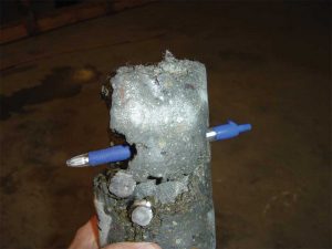
If water leaks are reported, injection materials are employed to fill voids and cracks within the shotcrete. With the numerous amounts of voids that can be typical with shotcrete, it can be difficult to precisely locate the initial point of water penetration. In the event of a warranty claim, manufacturers will often core the foundation walls to verify the shotcrete is well consolidated. Voids can nullify the waterproofing warranty.
Mockup
Following ACI 506, Guide to Shotcrete, preconstruction testing by means of a full-scale mockup is strongly recommended. The mockup should reflect the project-specific wall substrate, waterproofing and reinforcement conditions, and mimic the onsite logistical conditions. It is not unusual to have several mockup trials to optimize the system and prove the design works. Additionally, the mockup allows the nozzler to train and qualify under project-specific conditions.
Further, proper shooting procedures and application sequence should be laid out in writing in the work plan and tested at the preconstruction mockup stage.
One blind-side wall element that is good to have in the mockup is a box out of a tie-back because it is notorious for water ingress. A separate mockup may be required to facilitate this detail, as this element is large.
Since the mockup is not part of the work and the backside can be accessible, it is recommended to inspect the back of the shotcrete mockup panel for rebound or overspray entrapment or other visible imperfections not necessarily found by reviewing the cores.
In addition to the routine material quality tests, such as compressive strength required by project specification, visual examination of shotcrete cores is an important tool for quality evaluation. This type of examination can reveal imperfections, including voids, sand lenses, and delaminations, and the degree of reinforcing steel encapsulation.
ACI also publishes 506.2-13 (18), Specification for Shotcrete. However, in the opinion of the authors, one important quality assurance item no longer included in the ACI specification is the shotcrete core grades, as published in ACI 506.2-95.
In ACI 506.2-95, there were five specific shotcrete core grades. Grade 1 was defined as a solid specimen with no laminations, sandy areas, or voids behind the reinforcement steel. A Grade 2 specimen had no more than two laminations or sandy areas with dimensions exceeding 3 x 25 mm (1/8 x 1 in.). The height, width, and depth of voids shall not exceed 9 mm (3/8 in.). Porous areas behind reinforcing steel will not be more than 13 mm (1/2 in.) in any direction except along the length of the reinforcing steel. A Grade 3 specimen shall have no more than two laminations or sandy areas with dimensions exceeding 8 x 32 mm (3/16 x 1 1/4 in.) long, or one major void, sand pocket, or lamination containing loosely bonded sand not exceeding 16 x 32 mm (5/8 x 1 1/4 in.) in width. Core grades 4 and 5 have numerous large voids and sandy areas greater than that of Grade 3. It was generally practiced for applications, especially in hydrostatic ground water conditions, that a mean core grade of 2.5 or less was suitable. No single core is allowed to score greater than three, and passing requires an average score of 2.5, unless otherwise specified.
 [5]
[5]The project should not start the work until the contractor has proven its means and methods can provide the specified quality of shotcrete.
Three major issues
There are three primary installation issues with shotcrete that can have a negative impact on the performance of the waterproofing system. They are:
- voids around reinforcement;
- shotcrete overspray; and
- porous rebound pockets.
Stabilizing the reinforcement to prevent voids
Stabilizing the steel reinforcement in the wall with anchors is critical to keep it from moving or vibrating during the application of shotcrete. Vibrations in the reinforcing steel can create voids around the rebar, which reduces in-place strengths.
Sufficient anchors must be provided to rigidly hold reinforcement in place. Anchors or spacers should be located to offer sufficient clearance around the reinforcement, permit proper cover, and complete encasement with sound shotcrete. The intersecting reinforcing bars should be tied rigidly to one another and to the anchors to prevent vibration during shotcrete placement.
ACI 506.2-13 (18) only says, “Secure reinforcement to prevent movement.” This vague guidance has resulted in contractors initially installing a limited quantity of anchors only to have to add more during the shotcrete application. Of primary concern with this work sequence is the waterproofing contractor is unable to properly detail the new anchor points, which could be the source of future water leaks.
Some or all of the rebar attachment rods and fasteners may vibrate during the installation of rebar and subsequent shotcreting. With this in mind, all rebar attachment hardware should be detailed in accordance with the waterproofing manufacturer’s installation guidelines prior to shotcreting.
Although sufficient impact velocity ensures shotcrete flows around reinforcement, the rebar density of columns and pilasters create a potential for poor consolidation and the creation of voids in the structural wall, thus increasing the risk of water ingress. Due to these issues, designers may want to consider specifying CIP formed concrete for heavily reinforced columns and pilasters. They would be blocked out and cast-in-place before shotcreting the wall sections.
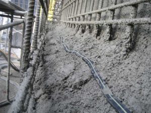
 [6]
[6]Insufficient shotcrete impact velocity assists with buildup of mix material on the reinforcement steel, resulting in a larger shadow void or porous area cast behind the rebar.
Poor reinforcement encapsulation reduces the quality of the shotcrete and increases the likelihood of water ingress.
Overspray and porous rebound
ACI defines overspray as “waste shotcrete material deposited away from intended receiving surface” and rebound as “shotcrete material that ricochets off the receiving surface,” both of which are, for all practical purposes, considered defects. When the nozzle is directed at an angle to the receiving surface, the shotcrete material can separate, creating additional rebounding and overspraying. When the nozzle is held at too great an angle to perpendicular, the shotcrete can trap greater amounts of rebound, overspray, and have poor surface bond.
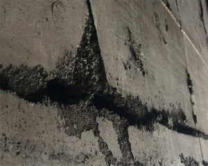
With regards to waterproofing, overspray can have negative performance consequences. For example, when constructing a working lift, the exposed waterproofing membrane directly above the planned lift height generally gets covered with a thin layer of overspray. As mentioned earlier, this thin overspray bonds to the membrane and forms its initial set with the working lift. Then during the application of the next working lift the subsequent shotcrete covers the overspray (it is important to note the second-lift shotcrete does not always bond to the initial layerof overspray). Thus, just above the lift joint, the waterproofing membrane may only be bonded to the overspray and not the shotcrete wall.
This overspray issue is not supposed to happen, but it does on many projects because protection from shotcrete overspray is rarely implemented in the field.
Temporary protection from shotcrete overspray and rebound should be installed directly above and around the shotcrete lift joint. This overspray protection can be plastic sheeting, cardboard, plywood, or other appropriate means to minimize the shotcrete splatter from attaching to exposed waterproofing. If temporary protection is infeasible, overspray should be removed before it hardens.
Also, when the shotcrete mixture is applied to a surface, the aggregate tends to ricochet off the receiving surface until sufficient cementitious paste builds up to absorb it. A nozzler’s helper should remove rebound that does not fall clear of the work, especially anything entrapped behind rebar, by using a blowpipe. Unremoved rebound can be porous, and yet another pathway for water migration.
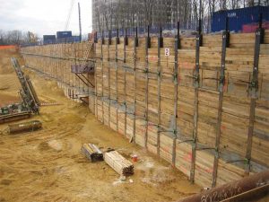
Support excavation preparation
Before the application of the waterproofing membrane and shotcrete, the support of excavation (SOE) shoring wall should be properly constructed in planar condition. Installation of shotcrete on waterproofing membranes installed on shoring walls presents placement and consolidation challenges. Additionally, if the project was valued engineered from CIP to shotcrete, and the shoring retention wall was built with the understanding CIP would be used, there can be even more challenges to shotcrete placement.
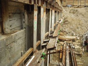
With soldier pile and timber lagging SOE, it is critical the latter is positioned on the inward-most H-pile flange to provide the most planar substrate surface possible. Placement of the timber lagging on the outward H-pile flange or mid-depth between the two H-pile flanges should be avoided because it is nearly impossible to properly place and also consolidate shotcrete behind the metal flange of the H-pile.
 [7]
[7]Timber lagging shoring walls should not have wide gaps between members. Wide gaps create a spot for the high-velocity shotcrete to blow open the overlap seam (even taped ones) of a waterproofing membrane. If the timber lagging is installed with wide gaps, the shoring wall can be brought to a sound and planar condition by applying a thin, fiber-reinforced layer of smoothing shotcrete, or by installing a course of cementitious boards over the face of the lagging. It is best to avoid using low compressive strength expanded polystyrene (EPS) foam insulation or any other soft material to prepare the substrate surface because it can compress or vibrate during shotcrete application.
Contiguous concrete caisson and cut rock face SOE can be brought to a planar surface to install the waterproofing by applying a smoothing course of shotcrete. With corrugated metal sheet piling, a course of plywood can be constructed on the surface of the metal spanning the concave recesses of the sheet piling. The plywood should be of sufficient thickness and braced to provide the required stiffness to place the shotcrete without vibrating. Also, the void space behind the plywood should be filled with compacted backfill or slurry grout. Without a plywood course it is difficult for the crew to place and properly consolidate the shotcrete and remove any rebound in the angled, concave void space through the reinforcement steel. Further, erecting a planar plywood substrate over the corrugated metal sheet piling can decrease the total quantity of waterproofing membrane by approximately 30 percent and facilitate an easier installation because it eliminates fixing the membrane in the deep, angled recesses of the metal sheet piling.
Tie-backs are another element to properly detail. Waterproofing permanent versus temporary tie-backs use different methods and detailing because the latter must be ‘blocked out’ and completed after the wall is constructed. Stay-in-place forming should not be used to keep the block-out open during shotcreting. It is very difficult to seal off against water ingress, especially with shotcrete. Instead, it is advisable to construct the box out with removable concrete forming tubes or wood. The top side of the box out can be slanted slightly upward to allow entrapped air to escape during final concreting of the tie-back.
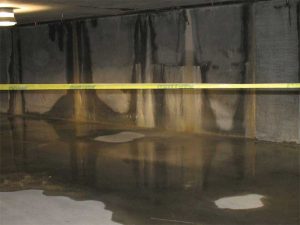
Any seeping or running groundwater from the retained earth should be controlled and channeled off before and during shotcrete placement. The buildup of water pressure needs to be prevented by using drainage mats, weep pipes, or similar measures. Puddling, ponding, and freestanding water should be avoided.
A difficult condition to address is when a below-grade, raised slab is placed prior to the shotcreting of the shoring wall (e.g. a slab between different parking levels). With this construction, sequencing the top corner just under the slab is a trap for rebound pockets and overspray. Thus, this area is poorly consolidated and prone to leaks.
 [8]
[8]Waterproofing systems
It is generally known in the waterproofing industry the majority of leaks in western United States over the past few years have been on projects with structural shotcrete placement on below-grade, blind-side foundation walls.
Historically, waterproofing manufacturers developed systems for use with conventional CIP formed concrete—they were designed for both backfilled wall and blind-side applications. Many of them are now being used with shotcrete, and this may be one of the reasons for more water ingress on shotcrete projects than conventional CIP concrete ones.
Since it is problematic to make shotcrete watertight, manufacturers have either modified existing systems or developed new materials. On some projects, waterproofing consultants have unilaterally added detailing and ancillary products to existing systems within their specifications as a means to adapt traditional CIP waterproofing assemblies to fair better with shotcrete. In some cases, this unilateral means has resulted in conflicts with warranties because either the detailing was not the standard guidance by the manufacturer or the ancillary product was not supplied by them.
Waterproofing membrane sheets are mechanically hung from the shoring wall. Like any sheet in a vertical application with minimal fasteners, the membrane billows away from the solid backing of the shoring in many areas. With CIP, formwork is installed inward of the lagging to place the foundation wall, and normal weight concrete is poured into the formwork. The weight of the concrete pushes the membrane tight against the shoring, and vibrating consolidates it. The pneumatic placement of shotcrete often results in the mix simply bouncing off the billowed membrane, leaving voids between the membrane and shoring, and preventing uniform confinement. These voids can also compromise the stability of fully adhered membranes because hydrostatic pressure buildup can force the membrane to span a void, causing seam failure.
The maximum spacing of the anchor points must be designed properly and should be tested in a mockup. Too much sagging or spanning of the membrane between the fastener points must be avoided. The substrate should be inspected (including but not limited to pillowing and spanning) before the installation of the waterproofing membrane and shotcrete. Also, shotcrete application has the potential to force open membrane lap seams as the high-velocity shotcrete is blasted against the waterproofing and discharged at varying angles in an attempt to fully encapsulate the steel reinforcement.
While admixture-type waterproofing products have performed well in CIP concrete, there are doubts about whether they can be relied on to perform in a watertight manner in shotcrete applications. Voids and large cracks must be limited for the admixture waterproofing to perform in a watertight manner in shotcrete applications.
Ancillary material – waterstop
Due to the likely development of porous sections in shotcrete, it is good practice to specify and install both swelling strip and injectable hose waterstops in all planned concrete cold joints. The swelling strip waterstop would be either bentonite or hydrophilic rubber, and be positioned outward of the injectable hose line. Although the shotcrete industry does not consider a lift joint to be a concrete cold joint, a swelling strip waterstop can also be placed in the top of a working lift by partially pressing it into the plastic concrete. Polyvinyl chloride (PVC)-P dumbbell waterstops are not used with shotcrete construction because its wide flange obstructs the application of shotcrete, and can result with poor consolidation behind it.
Conclusion
The use of structural shotcrete to construct below-grade, blind-side foundation walls is advancing throughout the country. However, inherent quality issues with shotcrete have resulted in the industry experiencing a high rate of water ingress. Today, shotcrete is considered a primary contributing factor to the failure of below-grade waterproofing systems. Manufacturers are starting to address the issues with shotcrete by developing new systems or by adding ancillary products and detailing.
With regards to waterproofing performance, conventional CIP formed concrete has proven to be more reliable than shotcrete. If conventional CIP formed concrete is value engineered out to shotcrete, it is advisable to review the waterproofing system to confirm it is suitable for the unique application conditions associated with shotcrete. It is important to also verify if the manufacturer has specific installation guidance and details for shotcrete.
![]() [9]Stacy Byrd, CDT, is the global technical services director at CETCO, a manufacturer of waterproofing, green roof systems, composite drainage, and waterstops. He has 30 years of waterproofing design experience. Byrd is an active member of ASTM International Committee D08 on Roofing and Waterproofing. He can be reached via e-mail at stacy.byrd@mineralstech.com[10].
[9]Stacy Byrd, CDT, is the global technical services director at CETCO, a manufacturer of waterproofing, green roof systems, composite drainage, and waterstops. He has 30 years of waterproofing design experience. Byrd is an active member of ASTM International Committee D08 on Roofing and Waterproofing. He can be reached via e-mail at stacy.byrd@mineralstech.com[10].
![]() [11]Kevin P. Kling is the technical sales manager for CETCO waterproofing system. Kling is based in northern Illinois. Prior to his current sales role, Kling conducted quality assurance review of below-grade waterproofing installations throughout the United States and Canada as part of CETCO’s warranty program. He can be reached via e-mail at kevin.kling@mineralstech.com[12].
[11]Kevin P. Kling is the technical sales manager for CETCO waterproofing system. Kling is based in northern Illinois. Prior to his current sales role, Kling conducted quality assurance review of below-grade waterproofing installations throughout the United States and Canada as part of CETCO’s warranty program. He can be reached via e-mail at kevin.kling@mineralstech.com[12].
- [Image]: https://www.constructionspecifier.com/wp-content/uploads/2020/02/Photo-1b-Applying-Shotcrete.jpg
- [Image]: https://www.constructionspecifier.com/wp-content/uploads/2020/02/Photo-1a-Shotcrete-SOE-application.jpg
- [Image]: https://www.constructionspecifier.com/wp-content/uploads/2020/02/Photo-3-Shotcrete-Core-with-Pen.jpg
- [Image]: https://www.constructionspecifier.com/wp-content/uploads/2020/02/Photo-2-Bad-Shotcrete-Lift-Joint.jpg
- [Image]: https://www.constructionspecifier.com/wp-content/uploads/2020/02/Photo-4-Back-lagged-SOE-wall.jpg
- [Image]: https://www.constructionspecifier.com/wp-content/uploads/2020/02/Photo-5-Good-SOE-Lagging-Wall.jpg
- [Image]: https://www.constructionspecifier.com/wp-content/uploads/2020/02/Photo-6-admixture-2.jpg
- [Image]: https://www.constructionspecifier.com/wp-content/uploads/2020/02/Photo-7-Bentonite-strip-waterstop-in-shotcrete-lift-joint.jpg
- [Image]: https://www.constructionspecifier.com/wp-content/uploads/2020/02/Stacy-Byrd-IMG_6220.jpg
- stacy.byrd@mineralstech.com: mailto:stacy.byrd@mineralstech.com
- [Image]: https://www.constructionspecifier.com/wp-content/uploads/2020/02/Headshot.jpg
- kevin.kling@mineralstech.com: mailto:kevin.kling@mineralstech.com
Source URL: https://www.constructionspecifier.com/issues-with-waterproofing-blind-side-shotcrete-foundation-walls/