

Vapor/air barrier continuity
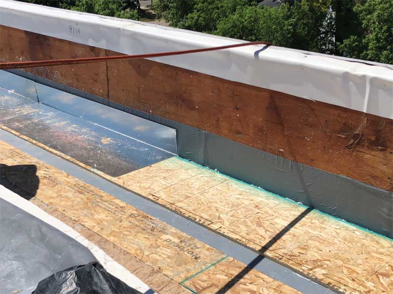
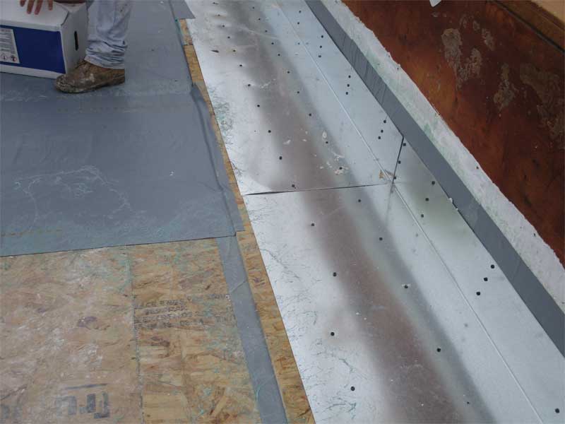
Vapor/air barrier continuity from the wall to the roof is the key consideration and the toughest challenge for the repair design. Installing the roof vapor/air barrier on top of the structural roof deck required transitioning the barrier through the deck to the rim area to complete the envelope. This was solved by designing a U-shaped sheet metal to wrap around the structural roof deck edge. This provides a surface on the bottom to receive the sprayfoam insulation applied to the rim area, and also a layer on top to which the self-adhering vapor/air barrier could be bonded.
Other considerations
Besides selecting the second option, other design considerations included:
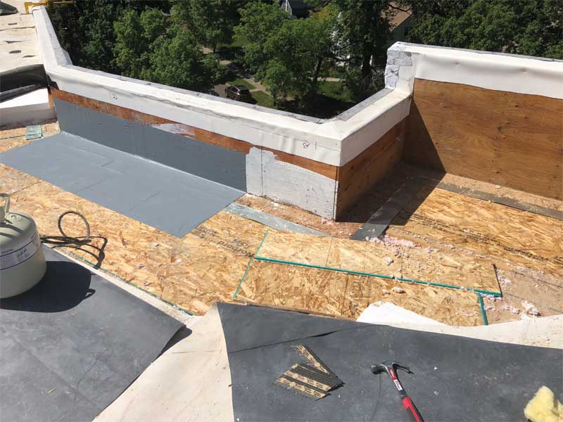
- the rim area had to be accessed from above, requiring the removal of some of the structural roof deck and blown-in insulation along the roof edge parapet;
- parapet varies in height, with some of the low parapet design being challenged by the additional insulation thickness;
- trusses run parallel and perpendicular to the parapet, which causes variations in the rim area conditions;
- structural roof deck removal along the parapets compromised the structural integrity of the roof perimeter at some conditions, so an engineered solution, including continuous steel angles and the addition of plywood sheathing to reinforce the structure, was required;
- an allowance was included in the base bid for deck and blown-in insulation replacement (the allowance amount was an educated estimate of how much replacement would be required based on the previous investigation work, and unit prices were requested to be used to charge against this allowance); and
- during the design process, input was provided by a local roofing contractor (collaboration amongst the contractor, owner, and the architect/engineer [A/E] helped develop a constructible design that achieved the goals and minimized costs and delays).
Construction challenges
Three contractors were invited to bid the project, and they provided input during the bidding process. One key, high-risk factor in constructing the second option was that doing all the work from the top side would leave the roof open and at the mercy of the weather for a substantial portion of time each day. Some days had greater exposure than others, depending on the amount of deck and blown-in insulation being replaced.
During the design phase, based on investigation-generated test results and observations, it was decided to make 60 invasive inspection openings prior to the start of construction to provide an idea of where the deck and insulation would need to be replaced (Figure 4). This would help the contractor better plan the construction work. The contractor awarded the reroofing project would make and repair the inspection openings.
Since litigation had been initiated, parties that were involved with the original construction had an interest in observing the existing construction. To minimize the disruption to the contractor’s operations, all interested parties were allowed to observe and conduct moisture testing at each of the 60 invasive inspection openings. The owner hired an environmental consulting firm to conduct moisture tests and sampling for fungal analysis on its behalf. This consultant provided a report including a roof plan showing the test results.
Moisture content
Based on the 60 invasive inspection openings, test results, and observations, a roof plan was developed showing the approximate areas where roof deck sheathing and blown-in insulation would most likely require replacement (Figure 5). The final determination of what needed replacement would be made by the contractor when each area was opened daily. While onsite performing their periodic observations, the A/E assisted the contractor to determine what needed to be replaced. A hand-held moisture meter was utilized daily to determine the moisture content of the OSB structural roof deck. Industry convention indicates 16 percent moisture content would be the threshold for requiring replacement.
The moisture meter did not provide useful readings for determining the need to replace the blown-in fiberglass insulation. Samples of insulation were taken to determine oven-dried moisture content by weight in order to develop a correlation with the moisture meter readings. A correlation could not be determined, so the decision to replace insulation was somewhat subjective. Wherever mold was detected on the OSB deck, the underlying insulation was replaced since mold spores can migrate into the insulation. The contractor also determined whether excess moisture was present by sight and touch.

