Keeping low-slope roofs dry in northern climates
by sadia_badhon | April 30, 2020 1:57 pm
by Dwight D. Benoy, PE, Pamela Jergenson, CCS, CCCA, BECxP, CxA+BE, and Gary C. Patrick, AIA, RRC, CSI
 [1]
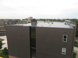
[1]When three separate wood-frame structures in the northern United States showed evidence of possible moisture infiltration in the roof areas, an independent architectural/engineering consulting firm was called in to confirm the issue was present, determine the amount of damage, find the source, and design solutions. All three buildings had been built within the last 10 years, and shared similar design characteristics, with commercial space on the first floor and apartments on the upper levels. When all three assessments had uncovered premature failures to some structural components of the roof assemblies as a result of accumulated moisture in the truss space, a thorough investigation into the source had to be conducted.
Background
All three buildings had similar non-ventilated, low-slope roof assemblies utilizing wood trusses with a polyethylene vapor retarder on the bottom of the trusses covered with a gypsum ceiling. Blown-in fiberglass or cellulose insulation filled the truss space from the ceiling to the bottom of the roof deck on all three buildings. Oriented strand board (OSB) of 13-mm (1/2-in.) thickness was installed over the trusses as the roof deck. Rigid board insulation was installed over the OSB, followed by the roof membrane, which was a gravel-surfaced built-up roof in one case, a ballasted ethylene propylene diene terpolymer (EPDM) single-ply membrane on another, and a mechanically fastened thermoplastic polyolefin (TPO) single-ply membrane on the third.
 [2]
[2]Images courtesy Inspec
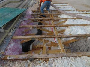
Water intrusion was not evident in any of the buildings. A survey of the roof surfaces showed they were in good condition. Occupants in two of the buildings reported mold issues, which led to further investigation. Maintenance people walked on the roof of the third building and discovered soft spots, which turned out to be locations where the OSB roof deck had lost its structural integrity due to moisture degradation.
It was apparent moisture-laden air had migrated into the truss space of all three buildings and condensed in the upper reaches of the roof assemblies. This resulted in excessive moisture buildup, mold, and rot of the OSB structural roof deck and structural trusses in a substantial portion of the roof area.
 [3]
[3]Ideally, the vapor retarder should act to minimize the amount of moisture vapor from the interior of the buildings getting into this space. In the northern climate where these projects were located, the vapor drive in the winter is mainly from the warm interior to the cold exterior. The warm interior air carries moisture vapor that will condense on surfaces below the dewpoint, the temperature at which condensation can occur.
The investigations found many bypasses in the vapor retarder that would allow the warm, moist interior air to migrate into the truss space. The party walls between apartment units, which were a double-stud wall construction, interrupted the continuity of the vapor retarder.
Similarly, all interior partition walls resulted in a discontinuity in the vapor retarder at the ceiling. This was exacerbated by the penetrations through the top plate of the wall by plumbing stacks and wiring. Penetrations through the ceiling, such as sprinkler heads and electrical boxes for light fixtures, were also found unsealed to the vapor retarder.
Two of the buildings had ducts from bathroom and dryer vents running through the truss space. Some of these ducts were not well-sealed at the joints, thereby introducing moist air directly into a space with a potential for condensation.
 [4]
[4]In the authors’ opinion, the roof assembly would perform satisfactorily if the ceiling vapor retarder were perfectly constructed. However, in this type of construction, it was impossible to perfectly construct a vapor retarder at the ceiling level because of the discontinuities. Ventilation of the truss space is an ineffective option to manage moisture. Unlike a steep-slope attic space, there is very little, if any, room to create airflow over relatively long distances.
Perhaps, the motivation to design an assembly as such would be to minimize the insulation costs related to the energy code requirements of recent years. While the amount of insulation installed exceeds the code requirement, the material and labor to install it were less than a code-compliant insulation installed above the roof deck. Filling the truss space with noncombustible insulation also eliminated the need for firestopping and draftstopping as noted in the 2000 edition of the International Building Code (IBC), in force at the time these buildings were constructed.
 [5]
[5]Photos © Dwight Benoy
Installing the vapor retarder at the roof deck level affords a better opportunity to achieve a complete vapor retarder. This would be an easy way to provide continuity across party walls and to seal penetrations. The vapor retarder must also be continuous from the roof to the exterior walls. This might be accomplished by using sprayfoam insulation within the truss space at the exterior walls.
On one building, the Coborn Plaza Apartments in central Minnesota, the problem was discovered approximately five years after the building was constructed when tenants of the top-floor observed mold on the gypsum ceiling and complained of musty odors. A mold remediation project was undertaken and included removal of the gypsum ceiling, vapor/air barrier, and blown-in insulation. It was discovered the exhaust ducts for the bathroom and dryer vents were poorly installed in some of the units. These ducts ran through the structural trusses and exited the exterior walls through the rim area. This duct layout also bypassed the ceiling vapor/air barrier, contributing excessive moisture to the truss space.
 [6]
[6]Image courtesy Inspec
The remediation work included the cleaning and sealing of the ducts, which was thought to be the only cause of the problem at that time. The moldy framing and structural roof deck were cleaned and painted with an anti-microbial paint. Some of the rotted deck was reinforced from below with additional OSB sheathing and framing.
Inspection openings from the interior were then made to verify if the remediation was effective. Excessive moisture presence was discovered. It is important to know the moisture buildup had occurred in a matter of months following the remediation. Investigation began for another source of moisture. Hygrothermal modeling was conducted to confirm or deny the inadequacy of the vapor/air barrier. Results indicated a propensity for moisture to accumulate.
Designing the repairs
Due to the damages already experienced and the potential for more to develop, it was determined Coborn Plaza needed a full roof replacement. The primary challenge was to develop a complete vapor/air barrier below the dewpoint temperature that also tied into the wall’s vapor/air barrier in order to envelope the building.
Repair options were developed and hygrothermal modeling was conducted for all the ideas. The owner required all work to be conducted from above the ceiling to minimize disruption to the tenants.
 [7]
[7]Image courtesy Inspec.
Photo © Dwight Benoy
First option
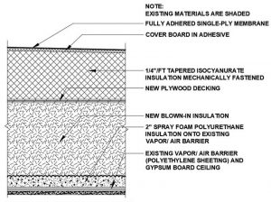
This option was intended to create a complete vapor/air barrier by installing sprayfoam over the polyethylene sheeting and bottom chord of the truss (Figure 1). This required the removal of the existing system down to the structural roof deck and also a significant portion of the deck to facilitate the vacuuming of the existing blown-in insulation out of the truss space and the installation of sprayfoam and new blown-in insulation. New tapered insulation and roof membrane above the structural roof deck were part of this solution.
Second option
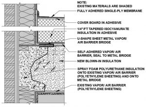
The second option required removal of the existing system down to the structural roof deck and the replacement of any wet, rotted, and/or moldy deck and blown-in insulation (Figure 2). A roof vapor/air barrier would be applied on the structural roof deck.
 [8]
[8]Photos courtesy Inspec. Photos © Matt Bryan
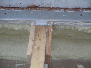
The application of sprayfoam insulation of at least 76-mm (3-in.) thick to the rim area was determined to be the most effective way in-situ to transition the polyethylene sheeting from the exterior walls to the roof vapor/air barrier. The rim area is at the top of the exterior walls at the level of the 406-mm (16-in.) deep roof trusses.
Sufficient insulation needed to be added above the structural roof deck to get the dewpoint temperature above the roof vapor/air barrier. This insulation also needed to be tapered to provide roof slope to the existing, interior, primary and overflow roof drains. The hygrothermal analysis showed a minimum of 102 mm (4 in.) of polyisocyanurate (ISO) insulation was required in order to keep the dewpoint temperature above the roof vapor/air barrier. This meant all roof drains would need to be raised to accommodate the increased insulation thickness.
 [9]
[9]Third option
This option required removal of all the existing blown-in insulation in the truss space and installing a sprinkler system to satisfy the fire code. A new roof assembly above the structural roof deck included a roof vapor/air barrier, tapered rigid board insulation, and membrane. This helped to let the dewpoint temperature occur above the roof vapor/air barrier and minimize the amount of insulation. This option also required sprayfoam in the rim area, as described in the second option.
The third option was quickly eliminated from further consideration because the owner decided against installing a fire sprinkler system above the top-floor ceiling due to the considerable disruption to occupants and the cost. Therefore, the blown-in insulation in the truss space needed to be maintained by selecting either the first or second option.
The solution
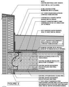
The second option was selected and developed into construction documents for bidding and construction (Figure 3). This was the best solution to achieve the goal of a complete vapor/air barrier. It also exposed the existing assembly to allow for the removal and remediation of wet, deteriorated, and moldy roof components. This option also maximized the reuse of the structural roof deck and blown-in insulation that was still in acceptable condition.
 [10]
[10]Vapor/air barrier continuity
Vapor/air barrier continuity from the wall to the roof is the key consideration and the toughest challenge for the repair design. Installing the roof vapor/air barrier on top of the structural roof deck required transitioning the barrier through the deck to the rim area to complete the envelope. This was solved by designing a U-shaped sheet metal to wrap around the structural roof deck edge. This provides a surface on the bottom to receive the sprayfoam insulation applied to the rim area, and also a layer on top to which the self-adhering vapor/air barrier could be bonded.
Other considerations
Besides selecting the second option, other design considerations included:
- the rim area had to be accessed from above, requiring the removal of some of the structural roof deck and blown-in insulation along the roof edge parapet;
- parapet varies in height, with some of the low parapet design being challenged by the additional insulation thickness;
- trusses run parallel and perpendicular to the parapet, which causes variations in the rim area conditions;
- structural roof deck removal along the parapets compromised the structural integrity of the roof perimeter at some conditions, so an engineered solution, including continuous steel angles and the addition of plywood sheathing to reinforce the structure, was required;
- an allowance was included in the base bid for deck and blown-in insulation replacement (the allowance amount was an educated estimate of how much replacement would be required based on the previous investigation work, and unit prices were requested to be used to charge against this allowance); and
- during the design process, input was provided by a local roofing contractor (collaboration amongst the contractor, owner, and the architect/engineer [A/E] helped develop a constructible design that achieved the goals and minimized costs and delays).
 [11]
[11]Construction challenges
Three contractors were invited to bid the project, and they provided input during the bidding process. One key, high-risk factor in constructing the second option was that doing all the work from the top side would leave the roof open and at the mercy of the weather for a substantial portion of time each day. Some days had greater exposure than others, depending on the amount of deck and blown-in insulation being replaced.
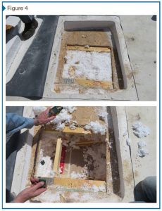
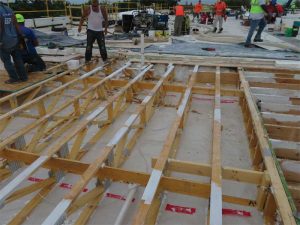
During the design phase, based on investigation-generated test results and observations, it was decided to make 60 invasive inspection openings prior to the start of construction to provide an idea of where the deck and insulation would need to be replaced (Figure 4). This would help the contractor better plan the construction work. The contractor awarded the reroofing project would make and repair the inspection openings.
 [12]
[12]Since litigation had been initiated, parties that were involved with the original construction had an interest in observing the existing construction. To minimize the disruption to the contractor’s operations, all interested parties were allowed to observe and conduct moisture testing at each of the 60 invasive inspection openings. The owner hired an environmental consulting firm to conduct moisture tests and sampling for fungal analysis on its behalf. This consultant provided a report including a roof plan showing the test results.
Moisture content
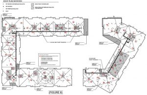
Based on the 60 invasive inspection openings, test results, and observations, a roof plan was developed showing the approximate areas where roof deck sheathing and blown-in insulation would most likely require replacement (Figure 5). The final determination of what needed replacement would be made by the contractor when each area was opened daily. While onsite performing their periodic observations, the A/E assisted the contractor to determine what needed to be replaced. A hand-held moisture meter was utilized daily to determine the moisture content of the OSB structural roof deck. Industry convention indicates 16 percent moisture content would be the threshold for requiring replacement.
The moisture meter did not provide useful readings for determining the need to replace the blown-in fiberglass insulation. Samples of insulation were taken to determine oven-dried moisture content by weight in order to develop a correlation with the moisture meter readings. A correlation could not be determined, so the decision to replace insulation was somewhat subjective. Wherever mold was detected on the OSB deck, the underlying insulation was replaced since mold spores can migrate into the insulation. The contractor also determined whether excess moisture was present by sight and touch.
 [13]
[13]Photos courtesy Inspec. Photos © Dwight Benoy
Construction
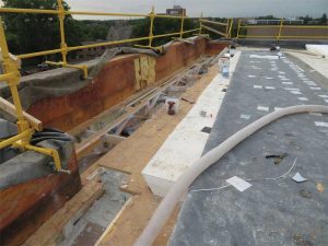
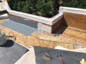
The contractor elected to work on the perimeter prior to conducting replacement work in the field of the roof (Figure 6). The former proved to be time-consuming and would have reduced the size of the area available for reroofing on a daily basis if the perimeter work was done in conjunction with the field of the roof. The contractor could also schedule the perimeter work on the days when unfavorable weather was forecasted, as the area could be enclosed rapidly should precipitation be imminent.
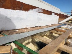
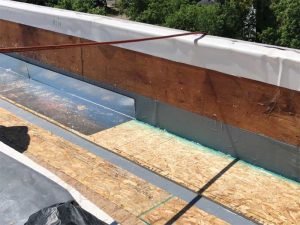
The contractor fabricated a Z-shaped transition metal instead of a U-shaped one. This served the same purpose as a vapor/air barrier transition material (Figure 7). However, there were areas of the previous mold remediation where additional framing done as part of that work interfered with the installation of the Z-shaped metal. Therefore, a two-piece, U-shaped metal was installed with the connection between the pieces accomplished with aluminum tape (Figure 8).
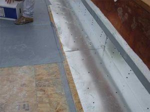
A short width of vapor/air barrier was then installed, followed by a parapet reinforcing assembly of plywood and sheet metal angle, and, lastly, the field of the roof vapor/air barrier (Figure 9).
 [14]
[14]The contractor had local insulation and plumbing subcontractors on call to complete varying amounts of work, depending on what was uncovered and anticipated each day. Perimeter work required the presence of the insulation subcontractor to vacuum insulation and install sprayfoam (in the rim area) and new blown-in insulation (Figure 10).
Mold remediation was handled by the contractor, alleviating the need for a specialty contractor. This eliminated coordination and delay issues. The contractor cleaned any discolored areas that were within the limits for moisture content, and then painted them with an anti-microbial paint (Figure 11). Most of the parapet that was left in place was remediated when the perimeter work was being constructed, which proved to be the most efficient.
The estimated amount of existing roof deck sheeting removal, based on the 60 invasive inspections openings, was 743 m2 (8000 sf). The actual amount of existing roof deck sheeting removal was 557 m2 (6000 sf).
While conducting the invasive inspection openings, and subsequently during the reroofing work, it was observed the TPO roof membrane plates were severely corroded in much of the roof area. This reduced the wind-uplift resistance of the roof membrane. The contractor was conscious of the need to respond quickly should a high wind event occur. Fortunately, the reroofing work was completed without incident.
 [15]
[15]The contractor removed tear-off debris from the site daily. The debris was lowered by crane into dump trucks. New materials were hoisted daily with only a one- to two-day stockpile on the roof. The crane and roofing materials were staged on the streets running adjacent to the building, but only at certain locations, thereby resulted in long travel distances across the existing roof in some areas. The City of St. Cloud, Minnesota, allowed the streets to be temporarily closed. Access to the retail establishments and egress from nearby buildings was continuously maintained, but was an ongoing public safety challenge.
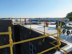
Perimeter safety was accomplished by attaching rails to the parapet (Figure 12). A safety monitor was also assigned to work with the crew applying the low-rise foam adhesive for the insulation attachment.
The fully adhered EPDM membrane over the tapered insulation system provided a fully draining roof with a finished appearance. Even with all of the construction challenges, the roof was completed in a timely manner.
Conclusion
The owner, contractor, and A/E worked together to achieve the goal of taking a sick building and making it well. All parties understood from the start shortcuts could not be taken. As with most projects, some surprises were encountered, but these were quickly resolved with input from all parties. Cost efficiencies were considered and implemented only if they did not compromise the design intent. The project was completed with minimal disruption to the operation of the building and its occupants.
![]() [16]Dwight D. Benoy, PE, was employed at Inspec, a building envelope consulting and engineering/architectural firm. He focuses his practice in forensic engineering of the building envelope. Benoy can be reached via e-mail at dbenoy@inspec.com[17].
[16]Dwight D. Benoy, PE, was employed at Inspec, a building envelope consulting and engineering/architectural firm. He focuses his practice in forensic engineering of the building envelope. Benoy can be reached via e-mail at dbenoy@inspec.com[17].
![]() [18]Gary C. Patrick, AIA, RRC, CSI, is an executive vice-president of Inspec, and has been with the company since 1977. He oversees the roofing services area of Inspec, which includes evaluations, design, peer reviews, construction observation and testing, and forensics. Patrick can be reached via e-mail at gpatrick@inspec.com[19].
[18]Gary C. Patrick, AIA, RRC, CSI, is an executive vice-president of Inspec, and has been with the company since 1977. He oversees the roofing services area of Inspec, which includes evaluations, design, peer reviews, construction observation and testing, and forensics. Patrick can be reached via e-mail at gpatrick@inspec.com[19].
![]() [20]Pamela Jergenson, CCS, CCCA, BECxP, CxA+BE, is a senior consultant for exterior walls with Inspec, a building envelope consulting engineering/architectural firm. She is an expert in hygrothermal analysis. She can be reached at pjergenson@inspec.com[21].
[20]Pamela Jergenson, CCS, CCCA, BECxP, CxA+BE, is a senior consultant for exterior walls with Inspec, a building envelope consulting engineering/architectural firm. She is an expert in hygrothermal analysis. She can be reached at pjergenson@inspec.com[21].
- [Image]: https://www.constructionspecifier.com/wp-content/uploads/2020/04/FIGURE-16.jpg
- [Image]: https://www.constructionspecifier.com/wp-content/uploads/2020/04/Figure-1-1-e1588262372494.jpg
- [Image]: https://www.constructionspecifier.com/wp-content/uploads/2020/04/Figure-2-1.jpg
- [Image]: https://www.constructionspecifier.com/wp-content/uploads/2020/04/Figure-3.jpg
- [Image]: https://www.constructionspecifier.com/wp-content/uploads/2020/04/Screen-Shot-2020-04-30-at-12.24.25-PM.jpg
- [Image]: https://www.constructionspecifier.com/wp-content/uploads/2020/04/FIGURE-6.jpg
- [Image]: https://www.constructionspecifier.com/wp-content/uploads/2020/04/figure-7.jpg
- [Image]: https://www.constructionspecifier.com/wp-content/uploads/2020/04/FIGURE-8.jpg
- [Image]: https://www.constructionspecifier.com/wp-content/uploads/2020/04/FIGURE-9.jpg
- [Image]: https://www.constructionspecifier.com/wp-content/uploads/2020/04/FIGURE-10.jpg
- [Image]: https://www.constructionspecifier.com/wp-content/uploads/2020/04/FIGURE-11.jpg
- [Image]: https://www.constructionspecifier.com/wp-content/uploads/2020/04/FIGURE-12.jpg
- [Image]: https://www.constructionspecifier.com/wp-content/uploads/2020/04/FIGURE-13.jpg
- [Image]: https://www.constructionspecifier.com/wp-content/uploads/2020/04/FIGURE-14.jpg
- [Image]: https://www.constructionspecifier.com/wp-content/uploads/2020/04/FIGURE-15.jpg
- [Image]: https://www.constructionspecifier.com/wp-content/uploads/2020/04/DWIGHT-BENOY-BIO.jpg
- dbenoy@inspec.com: mailto:dbenoy@inspec.com
- [Image]: https://www.constructionspecifier.com/wp-content/uploads/2020/04/GARY-PATRICK-BIO.jpg
- gpatrick@inspec.com: mailto:gpatrick@inspec.com
- [Image]: https://www.constructionspecifier.com/wp-content/uploads/2020/04/PAM-JERGENSON-BIO.jpg
- pjergenson@inspec.com: mailto:pjergenson@inspec.com
Source URL: https://www.constructionspecifier.com/keeping-low-slope-roofs-dry-in-northern-climates/