

It sounds counterintuitive, but in a cavity or drainage wall one assumes moisture will find its way into the cavity. Brick themselves do not leak, but water can find a way into the system.
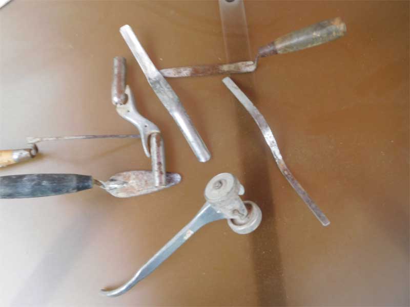
The first dissimilar material to investigate is the actual mortar joint. A mortar joint that is both tooled and compressed during installation is the first line of defense against moisture penetration. Figure 4 features a sample of mason tools used for tooling and compressing mortar joints.
Small hairline cracks in mortar joints are to be expected and should be no cause for alarm unless they grow to exceed roughly 1.5 mm (1/16 in.). In that case, it should be looked at as a possible source of moisture, and the problem should be addressed during routine maintenance.
Assuming some amount of moisture will enter the masonry cavity, the strategy is for moisture to drain down the back of the veneer to flashing and weep vents. Flashing materials, and their installation, are the source of many long and detailed articles, so for this discussion, the author only wants to point out some common mistakes.
First, laps can cause leaking. Since most flashing systems require a lap from one section to another, this is a natural place for problems to occur. It is advisable to check the lap size and whether appropriate sealants were used. Most manufacturers will recommend anywhere from 50 to 150 mm (2 to 6 in.) for the lap. Based on jobsite experience, IMI recommends a minimum lap of 150 mm. This reduces the possibility of moisture traveling underneath the lap and also gives additional room for the installer to have some tolerance.
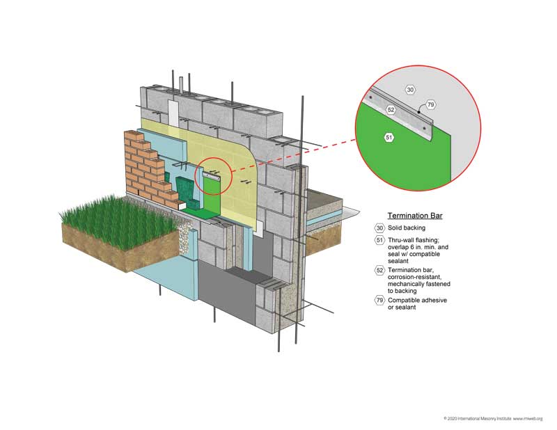
Check all flashings to see if there are penetrations. In many cases, the flashing is installed with the backup concrete masonry, with the intention to install the brick veneer later. This leaves some vulnerable types of flashing exposed to other trades prior to installation of the brick veneer. This can be addressed by either changing the sequencing or installing the flashing later with the brick veneer using a termination bar (Figure 5).
When using a termination bar, it is advisable to insist on a sealant bead across the top of the bar to resist water draining behind the flashing. Trade coordination in the masonry enclosure is critical.
Windows, doors, and changes in materials from brick to concrete, stone, glass, or metal are all potential areas for leaks. When two trades meet, there is always the possibility for a huge sealant joint due to tolerances or just poor coordination. This leads to another common issue: the size of the drainage plane, cavity, or air space itself. With various tolerances in the construction industry among steel, wood, concrete, and in the masonry itself, one needs some room in the cavity between the back of the brick and the face of the backup material. Building codes call for a 25-mm (1-in.) minimum cavity dimension. While this may seem generous, consider the various tolerances and the possibility for mortar droppings or other construction debris to fill a cavity. The author’s firm recommends a 50-mm air space independent of any insulation in the cavity. A 50-mm air space has positive effects, including:
- promoting airflow through the cavity, a first principle toward rainscreen construction; and
- allowing for some level of mortar droppings.

