Maintaining continuity at transitions
Detailing transitions for continuity
There are two crucial locations within a building to address when designing details: transitions and penetrations. Transitions occur between a change in plane or material, and penetrations are actual openings to the outside or inside of a wall. Both areas are at risk for lack of continuity in the insulation and water/air barrier, leading to thermal bridges, leaks, and poor performance. While every detail cannot be addressed in this article, an evaluation process may be initiated to help identify potential design problems.
Detailing a wall-to-roof transition
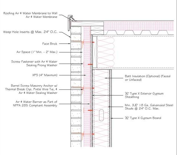
In the process of detail review, it is recommended to begin at the top of the building—the transition from wall to roof. Using the example of a gravel stop application (Figure 2), the first fundamental requiring scrutiny in this wall-to-roof transition is liquid moisture, which is addressed by ensuring the roofing air and water barrier or membrane is tied into the wall membrane.
Continuing down, weep holes are inserted at the top and bottom of the masonry veneer to accommodate liquid moisture, since they encourage the draining and drying of water and the movement of air. Weep hole inserts not only help keep the vents clear of debris, but they also indicate the ‘hole’ is intentional, so it is not mistakenly filled in if presumed to be a joint without mortar. The air space itself allows for air movement and therefore drying within the cavity, and has multiple fastener types present. These are anchors attaching cladding to structure and fasteners attaching insulation and sheathing to structure.
With regard to liquid moisture management, it is important to look for a fastener/washer product that can create a watertight seal or ‘gasket’ around the penetration in the water barrier, maintaining water resistance demonstrable by ASTM D1970, Standard Specification for Self-adhering Polymer-modified Bituminous Sheet Materials Used as Steep Roofing Underlayment for Ice Dam Protection, or ASTM E331 testing. Additionally, the cavity of a wall tends to be
a very wet location, so it is necessary to select a highly moisture-resistant insulation such as extruded polystyrene (XPS). Once each of these layers has been reviewed for liquid moisture management, one can analyze the wall for thermal comfort.
One should review heat control layers by identifying the insulation, and then double-checking as much continuity is maintained as possible. In the wall-to-roof transition example in Figure 2, there is continuous XPS insulation along the roofline, which transitions onto the wall itself, creating as few opportunities for thermal bridging as possible. Additional insulation is provided by fiberglass or mineral wool batts in the framing cavities.
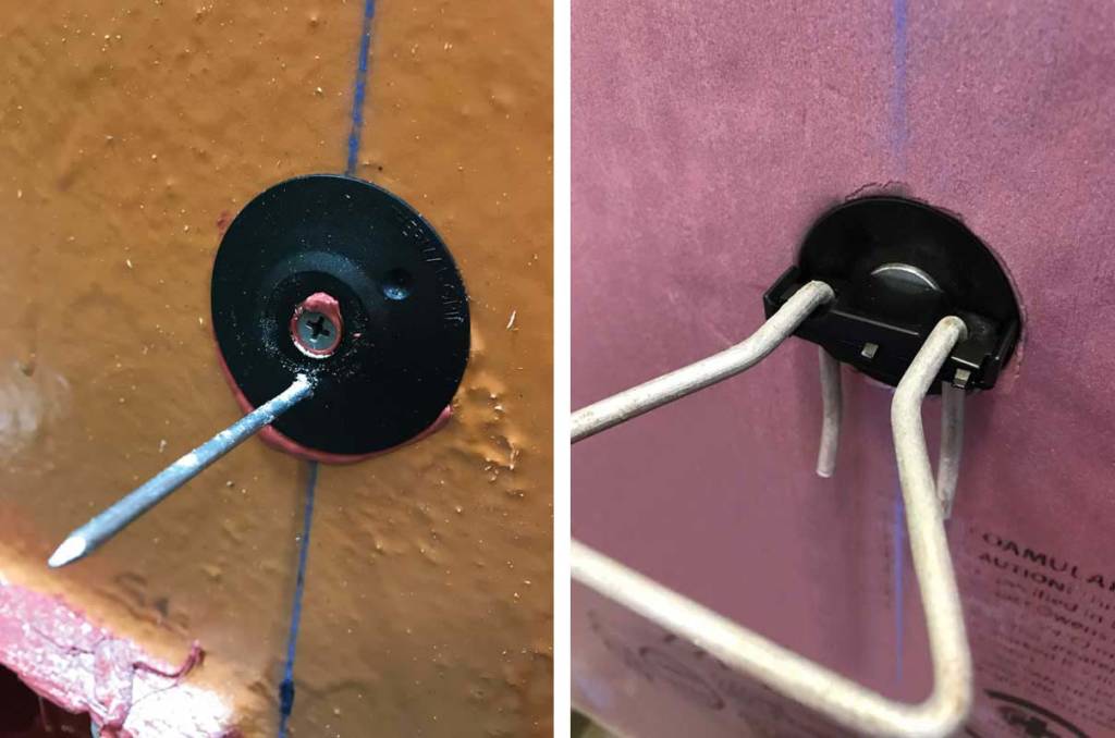
Photos courtesy Rodenthouse (left) and Heckmann Building Products (right)
It is important to note steel stud framing in particular is a significant thermal bridge through framing cavity insulation. Another critical factor to consider in the reduction of thermal bridging is selecting fasteners that are thermally interrupted and break the continuous energy conductance path through insulation layers (Figure 3).
The next building science fundamental to assess is air—how will air control be maintained through this particular wall-to-roof detail? With this in mind, one should revisit the air and water barrier to confirm it is continuous from the wall to the roof. Fasteners are again examined to ensure they are designed to reduce or eliminate air infiltration. Are they creating a gasketing effect and maintaining tightness around penetrations? It is crucial to remember these small products perform several different functions and can often be overlooked, but may contribute to potential leakage due to thousands of penetrations in the air and water barrier.
After air control is reviewed, one should address moisture as a vapor. Whether a vapor retarder is established or a vapor-permeable design is being used, it is critical to ensure continuity has been addressed and that materials do not create inconsistent levels of vapor transmission without the ability to prevent or dry condensation. One can start by looking at the membrane—both the roof membrane and the air and water barrier—since both will act as vapor retarders or vapor-permeable membranes. If the roof has a secondary vapor retarder and the air barrier is to act as one, it is important to ensure they are continuously attached.
Next, one should check the weep holes enable moisture vapor to escape the cavity and air to enter for drying. It is important for the air space to allow air in and vapor out to encourage drying rather than condensation accumulation within the wall. It is also important to look again to the fasteners penetrating any vapor control layers, such as the air and water barrier. Since insulation is where the temperature change occurs within a wall, it is critical to keep vapor away from temperatures causing it to revert to a liquid state. Alternatively, vapor can be blocked from reaching a lower temperature by a vapor retarder. This can be done via an individual product, the air barrier, or the insulation. While the example in Figure 3 is vapor-permeable, the decision of permeable versus impermeable membranes should be evaluated on each project and may be supported with hygrothermal analysis provided by consultants or some insulation manufacturers.
Next, one should examine fire resistance in each layer. Beginning at the roof, there may be a need to create a rated or classified roof assembly, impacting the membrane itself as well as the insulation. This roof will tie into the wall, which could be required to be NFPA 285-compliant. Both the CI—if it is a foam plastic—and a combustible air/water barrier trigger NFPA 285, and must be evaluated as part of that particular assembly of components.
Noncombustible mass components such as brick veneer or CMU, stone, and concrete contribute to resisting fire propagation in NFPA 285 testing. Employing this noncombustible mass cladding means XPS insulation is acceptable, though itself combustible. When a combustible cladding—such as metal composite material (MCM) or high-pressure laminate (HPL) panels—is chosen, a different insulation, such as mineral wool, would be required. Although these are understood concepts, it is best to verify the complete assembly has an NFPA 285-compliant evaluation, with consideration for the specific insulation and air barrier used.
Finally, when analyzing a wall-to-roof detail, professionals should review acoustic performance and any materials used that allow for the transfer of acoustic energy. (In Figure 2, face brick would be one such material.) The air space serves to transfer that energy and potentially amplify it, which is why a continuous air barrier contributes to acoustic performance, sealing small penetrations that otherwise may allow sound energy to penetrate.
With regard to fasteners, eliminating a thermal bridge also helps eliminate a path to transfer acoustic energy. Fiberglass batt and, to a lesser extent, foam plastic CI, are helpful in reducing acoustic energy transfer, as are many of the other components of the assembly. Staggered steel studs, multiple layers of gypsum sheathing, and resilient channels would also improve the acoustic performance of this assembly.
Sign up for our weekly newsletter
Architectural materials and methods delivered right to your inbox
- CSI News & Notes: CSI’s impact earns official recognition; celebrate leaders, mentors, and innovators; and more
- CSI News and Notes: CSI spring certification exams open; scholarships available; and more
- CSI News & Notes: CSI MSR heading to San Diego; spring certification exams open; and more
- To Be Specific: Why CDT Should Be Your First Move
- CSI News & Notes: CSI Fellows share member benefits; and a New Year’s Resolution to keep
Related Products

Read the Latest Issue